Dual x and y homing similar to g30 for multiple z screws
-
@killernoy you could, in which case you just map them together in M584 and you're done.
Would there not be any issue of both motors getting out of sync? -
@jay_s_uk said in Dual x and y homing similar to g30 for multiple z screws:
@killernoy you could, in which case you just map them together in M584 and you're done.
Would there not be any issue of both motors getting out of sync?
yes, as i am building it unaligned the tention on the rods connecting the carriages with the print head will pull it back into misalignment.
-
Do you mean to use M671 to define some points and then adjust based on how you probe the X/Y points?
Or just do some anti-racking to set points?
-
@phaedrux exactly. i would love to have the points predefined so that the board can calculate the corection needed. Is that possible or would i have to do some remapping trikery to make the printer think the x axis is a z axis with two leadscrews and then do the same for y?
-
@killernoy Right now I think you might have to do some remapping trickery to use the normal Z axis commands.
Is the frame so unsquare that it couldn't be used to adjust the X/Y?
-
@phaedrux That is not the point, the unalignment is unknown which is why i want to do the resquaring every time i home the machine and the easiest way to do that is to measuare the points and after that to adjust for the difference which is what the g30 comand does.
-
@Killernoy
there is a simple mechanical way to square the axis and avoid racking. I called it 'dual roller constraint' and with the right cable-routing you don't even have to adjust it.
Here is a small demo video demonstrating the anti-racking.Feel free to ask any questions, as the video isn't really selfexplaining...
-
@killernoy I'm not clear about your machine. Does it have two X homing switches and two Y homing switches? If not, what exactly is the arrangement of homing switches?
-
@killernoy said in Dual x and y homing similar to g30 for multiple z screws:
@phaedrux That is not the point, the unalignment is unknown which is why i want to do the resquaring every time i home the machine and the easiest way to do that is to measuare the points and after that to adjust for the difference which is what the g30 comand does.
Seems to me the easiest way is to install endstop sensors for each stepper and let the homing process align things.
Nothing to measure, the endstop sensors provide the reference points needed for alignment.
At least that is the way it works on my printers running 3.2.2.
Frederick
-
@dc42 i would appreciate a way to set an offset on one individual endstop when using dual endstops. As you're probably well aware, getting endstops in exactly the same place is damn near impossible
-
@jay_s_uk said in Dual x and y homing similar to g30 for multiple z screws:
@dc42 i would appreciate a way to set an offset on one individual endstop when using dual endstops. As you're probably well aware, getting endstops in exactly the same place is damn near impossible
What has been suggested in the past, by myself and others, is to not have G1 H1 operations set position based on M208 settings but have the position value(s) in the M574 command where the endstop(s) are configured.
Lacking that feature for now I have endstop sensor mounts that use a M3 screw for fine adjustment of the trigger position.
It might be possible to split the steppers after homing to allow tweaking the position of one and then "un-split" them.
Frederick
-
@fcwilt yea, i could easily split them and do it that way, just seems a step backwards
-
@jay_s_uk said in Dual x and y homing similar to g30 for multiple z screws:
@fcwilt yea, i could easily split them and do it that way, just seems a step backwards
I agree which is why I have suggested the change to putting the position settings to be used into the M574 commands.
There is nothing that should require the endstop trigger point to exactly match an M208 setting.
Frederick
-
@fcwilt I think you're always going to be stuck with the M208 limits e.g. if you X lower limit was 0 but your endstop was actually at -10, any movement t o get there that wasn't a homing move would be classed as trying to move outside the machine limits.
Maybe instead of setting anything with the endstops, there should be a way of moving a specific motor within a multidriver axis setup.
So home your axis and then adjust the position of one of the motors by a set amount after which they remain in sync -

@dc42 i currently have dual enstop mounts but want to have the mounts on the pint head in order to shorten the xy-motion systen by about 20mm in the z direction. -
@killernoy said in Dual x and y homing similar to g30 for multiple z screws:

@dc42 i currently have dual enstop mounts but want to have the mounts on the pint head in order to shorten the xy-motion systen by about 20mm in the z direction.Hi,
I have a similar setup but the endstop sensors are mounted on the frame.
They don't make the XY motion system larger in the Z direction than if I moved them to the printhead.
Can you show where they are mounted now on your printer and explain how moving them would save space?
Thanks.
-
@jay_s_uk said in Dual x and y homing similar to g30 for multiple z screws:
@fcwilt I think you're always going to be stuck with the M208 limits e.g. if you X lower limit was 0 but your endstop was actually at -10, any movement t o get there that wasn't a homing move would be classed as trying to move outside the machine limits.
True but generally moves made to trigger the endstops are homing moves.
In any case I was thinking of my printers which use beam-break IR sensors which typically trigger inside the M208 limits.
Maybe instead of setting anything with the endstops, there should be a way of moving a specific motor within a multidriver axis setup.
So home your axis and then adjust the position of one of the motors by a set amount after which they remain in syncThat could work but would be a very tiny bit less efficient then being able to have each endstop specify a different location.
Frederick
-

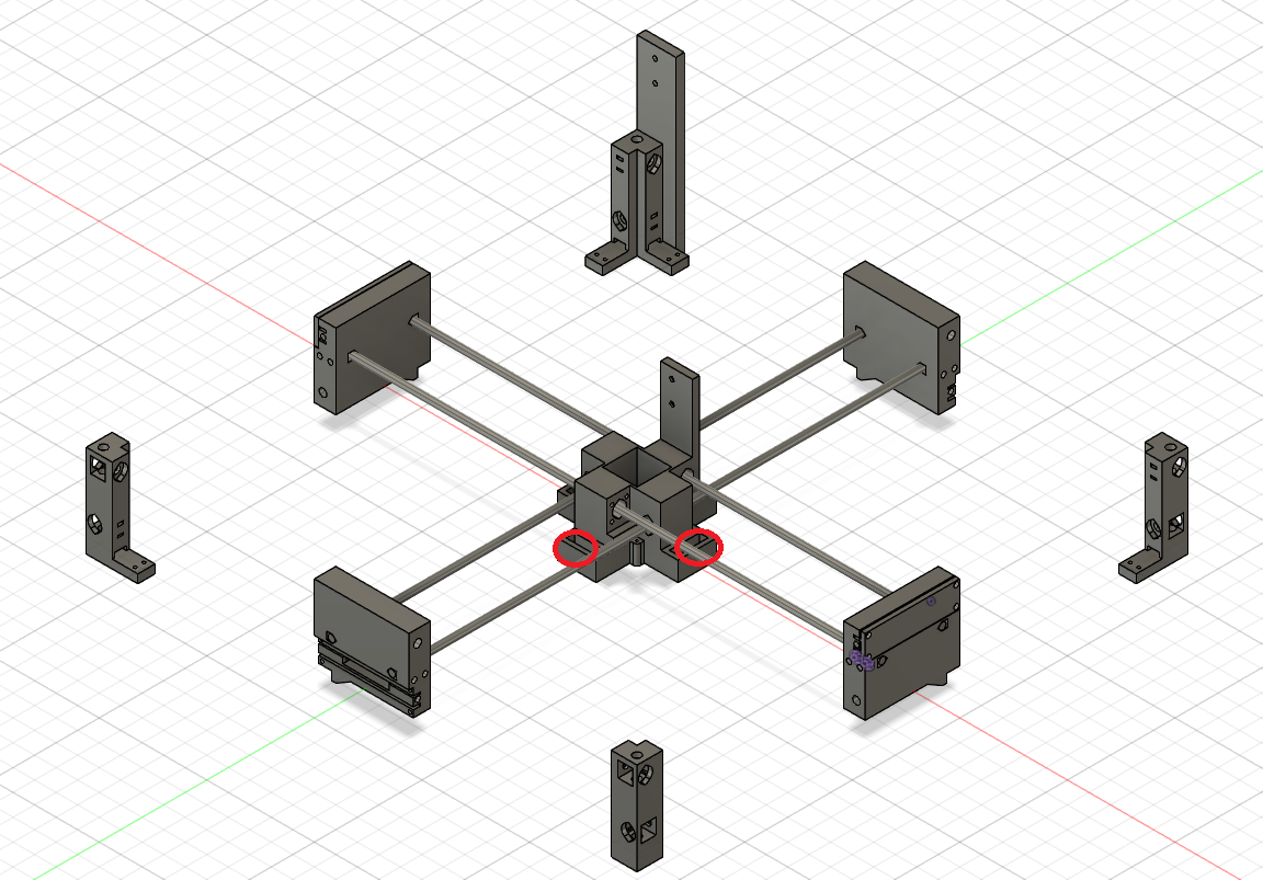
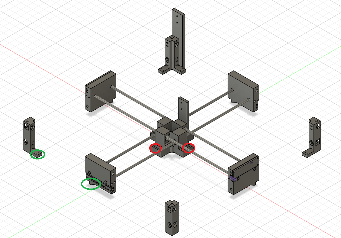
@fcwilt they are at the bottom of the corner pieces and are activated with a foot on the carriage and the entiere homing system is about 25mm high -
@killernoy said in Dual x and y homing similar to g30 for multiple z screws:

@fcwilt they are at the bottom of the corner pieces and are activated with a foot on the carriage and the entiere homing system is about 25mm highThanks.
If we had a picture showing all the parts it might answer my question - but we don't so I will ask.
Can you move the endstop sensors higher yet still keep them attached to same parts but on the outside?
Frederick
-
@fcwilt i will put them on the print head but this post was not about discussing where i want to put my endstops but to discuss options for compensative homing like the g30 for multiple leadscrews.