As I logged on to the forum this morning I had a realization or perhaps I was just having a "moment". For the majority of us this is a hobby. A passionate one at that. We lay in bed at night dreaming of that perfect print or a new design. Seeing all the challenges people face and then overcome I couldn't help but feel appreciation for the tireless efforts of David, Tony, the moderators and all the contributors driven by this passion. Thank you.
Personally I am challenged when it comes to the electronics/computer side of the machine. Hell, I didn't even own a computer until I was in my mid 20's yet because of the efforts of this organization I have been able to create some awesome stuff and plan to make more. Keep it up guys
Best posts made by 3DPMicro
-
Positive Rantposted in General Discussion
-
Duet controlled micro millposted in My Duet controlled machine
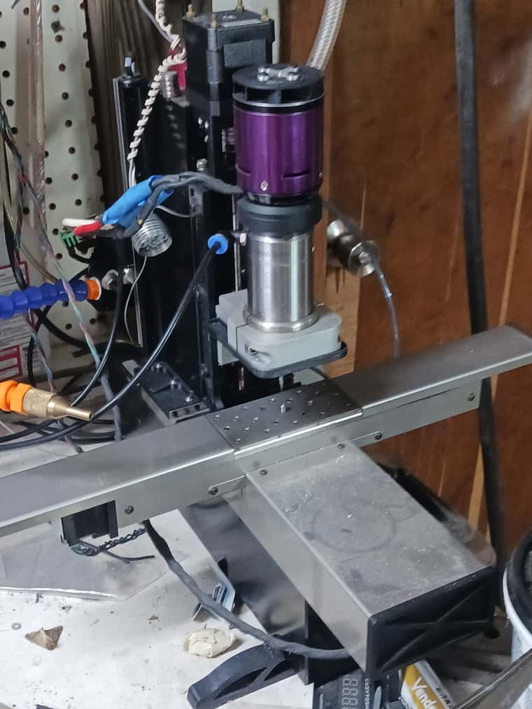
I've been working on this one for a couple months. Using Misumi LX20 actuators with 1mm lead ball screws driven by 1 amp, 1.8 nema 14's on x and y (10 kg of force) and a .9 nema 17 on the Z using 75 mm square, steel bar as the foundation. Tool is driven by a 150K RPM Nakanishi air spindle. The purpose of the build is high accuracy micro machining. I have just ran the first test part, a 9mm diameter sprocket, and it turned out phenomenal (inspecting it with a digital microscope). I plan to try some 3D contouring next and then find the limits in part sized using .5 and .25 mm end mills I have.


-
RE: Duet controlled micro millposted in My Duet controlled machine

I was able to get the motors to run over 1200 RPM (1200 mm/m travel speed) but while using my test program they stuttered when interpolating corners below a certain radius (G2/G3) with 16x ms, interpolated. Still almost silent and smooth at 8x Ms w/o interpolation. I went all over the place with Accel, and jerk with no apparent effect on the stuttering until down, around 600 mm/m. This 2.3 mm thick part took 14 minutes using a .81 mm end mill including interpolating the 6, 1 mm mounting holes. .1 mm axial DOC and 400 mm/m feed.
The demensions I can measure easily came out within .02 mmp.s. for the record i was not actually using the bathroom when I took the picture

-
RE: Duet controlled micro millposted in My Duet controlled machine
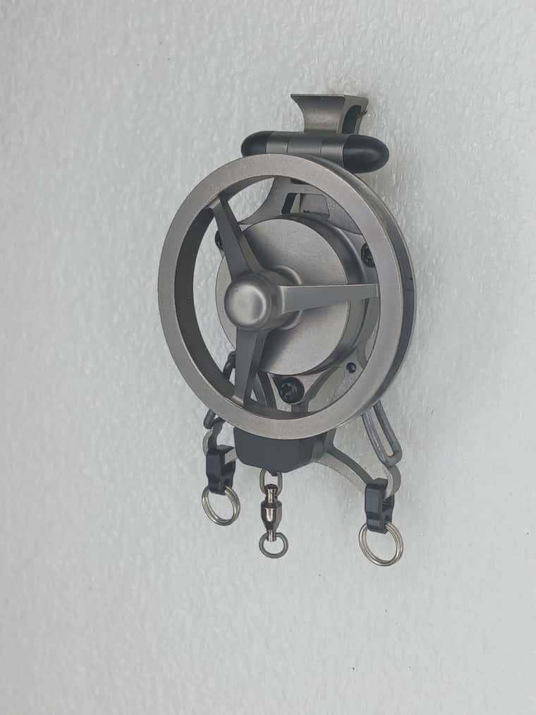
My little micro Mill has been working great. No hicups other than the PanelDue touch screen not always working right (too lazy to investigate). I make high precision machined parts at my job using $500k equipment and it still amazes me how accurate and repeatable this $800 machine is. Latest project was a gift I made for my parents 50th wedding anniversary. Using a 20 deg engraving bit with a .1mm tip the machine was consistently able to ablate the thin aluminum film from the backside of the mirror with only minor signs of etching the glass in a few places. This was after surfacing the spoil plate and verifying flatness within .005 mm. This tells me at least the Z is hitting the theoretical .003 mm resolution and doing it pretty darn consistently.

-
RE: Duet controlled micro millposted in My Duet controlled machine
The Duet 2, with regularily updated FW has been flawless through many projects over the last few years guiding this little mill. I have the same confidence in it as any of the professional grade machines I run at work.
I thought if it could be tripped up the g code for 3d maching the .5mm radii on this part would do it. Resolving moves as small as 100nm for the inside corners there was no indication of lost steps or rounding errors (the floating point goes that low?) over the 8 parts that were made. Pretty cool
https://youtu.be/27_E8RawCyQ
There were 0 hiccups and 0 errors but underruns showed 0,0,4. What does that mean? -
RE: Ground loops don't only affect 3D printersposted in Off Topic
Tail dragers can be equally frustrating because of a ground loop
")
-
RE: single block and feed holdposted in CNC
@miss-rebekah I'm a machinist too (30 years in aerospace) . I think it's important to realize the value in the Duet. I dont think it was ever intended to be a full feature cnc controller (although it is quite capable) rather the focus is on 3d printing. For less than $150 it is extremely powerful but it does lack a a tad in the cnc department but continualy improved. I assume if you are going single block you are not doing the programming were here you will program so you already know what the machine is supposed to do next. Although there is no feed hold (before the buffer runs out) that I am aware of you can set up an emergency stop button that will keep you from tearing anything up. If you want your router to act like your machine at work I would suggest looking at Acorn or Oak but be prepared to pay a lot more for those additional features you mentioned. I say give it a try and I'll think those few things will become a non issue. Duet and RRF is very user friendly once you get past the learning curve and it's all g code so I think you'll feel very comfortable with it.
-
Sanity Check Plz!!! Omron Inductive switch for XYZ endstopsposted in Duet Hardware and wiring
This is for a mill so no Z probing. I can get 3 of these dirt cheap https://www.ia.omron.com/product/item/1017/
and would like to use them on a new mill build. Here's my board info...
I see info here https://duet3d.dozuki.com/Wiki/Connecting_a_Z_probe#Section_Mode_Num_5
on how to connect as a Z probe but how do I hook them up for XYZ endstops?
Thanks -
RE: DWC won't open. What am I missing? Solvedposted in General Discussion
Just upload the DuetWebControl.zip file through the Settings General tab of DWC. It will be unzipped and the files will be put in the correct folders automatically.
I cant get the DWC to open
Latest posts made by 3DPMicro
-
RE: Duet Ethernet and BTT TMC5160T proposted in Duet Hardware and wiring
@droftarts thanks for taking the time to look at this. The remaining cfg pins are to set motor current. Its labeled on the back of the board but not in any documentation. I believe I have the other jumpers set correctly including Standalone mode. Tonight, I'll sketch up a simple schematic to show how the step stick adapter is labeled along with the voltages and a pic of the back. Probably too confusing to explain further without a visual representation.
-
Duet Ethernet and BTT TMC5160T proposted in Duet Hardware and wiring
Sorry in advance for the long post.
Before I invest in 6HC I wanted to see if the 5160's at 48v would provide the speeds I desire for non print moves. Im using my single axis test rig for this experiment. I already have several Duet Ethernets so I purchased the BTT drive as seen in this Amazon ad https://a.co/d/dh1Ueat with the intent of running it in "stand alone" mode. The wiring seems straightforward but I've yet to make it work. I have the motor supply connected to a 48v psu and the Duet on a 24v psu. Of course step, dir, en, grd, and 3.3v are connected to the Duets expansion header but it seems like the drive also requires 24v. The 7th slide in the ad shows "ordinary drive connector" pinout that I'm connecting to. If I connect 24v to that connector like it's marked, the 24v, 48v and logic will share a common ground. Does this seem safe? I don't want to kill the Duet. There's no literature that mentions specific wiring in Standalone mode. I did notice on the step stick adapter the 24v pin is marked Vm (for gate?) leading me to believe 24v is required for the circuitry to work but thats an ignorant guess. -
D3 magnetic encoder/1hcl max rpmposted in General Discussion
What would be the maximum motor rpm and are there factors that contribute to it?
Thanks -
RE: Very slight systematic waves every about 2mm on the printsposted in General Discussion
@luc since the 2mm spacing suggests its related to tooth pitch flip the belt so the teeth aren't engaged, tension to provide enough grip to execute a test print.
-
Removing axis in consoleposted in Duet Web Control
My 2 axis CNC lathe is finally approaching completion. Since I only need x and z can I remove the y axis from the console. If so, how?
Thanks -
Signal input helpposted in General Discussion
I'm using a VESC to control the BLDC spindle motor on my Duet Ethernet (FW=3.4) mill. Having recently configured a different spindle for the same mill using PWM I would like to set this one up to act like the other, i.e control through "spindle" in DWC and use M3 .... in my gcode program. Unfortunatly the VESC doesn't support PWM input. PPM, ADC (duty cycle), NRF (whatever that is) and UART are the options. Is there a path forward to making this happen? Thanks
-
RE: Measuring PWM output and duty cycleposted in General Discussion
@o_lampe I haven't tried it yet but if I put 5 Volts to the pwm lead to the spindle that should essentially be 100% duty or is the pwm from Duet pulsing the ground?
I tried much higher frequencies but it didn't have any effect. Im waiting to hear what the spindle manufacturer has to say
Can you give me an example of the converter you mentioned? Is it an A/D converter? -
RE: Measuring PWM output and duty cycleposted in General Discussion
I have my spindle working but it's not reaching the 10k rpm as advertised. I have tried 100-2000 for the frequency with no noticeable effect. Im consistently seeing a range of approximately 50% duty cycle at about 4500rpm to a maximum of 90-93% at 7450rpm (ballpark numbers). The oscope is bouncing around when in the 90+% range so im not sure if it's not seeing 100% duty cycle or if the Duet isn't actually producing it. 100% duty cycle should show as flat lined on the oscope or possibley a consistant waveform? It looks pretty rough.
Basically I'm trying to determine if the Duet is producing the highest possible duty cycle or the spindle is not capable of the advertised 10k rpm. Any input would be appreciated