Duet 2 Wifi and Geckodrive G320x on Stepper Channels 10 and 11
-
A couple of things I tried:
- Using Channel 11 instead of 10
- Increasing the timings from the above
I don't (currently) have access to an oscilloscope, is there any sort of probing I can do with a standard meter to check things out (with the understanding that sensing the steps would be a challenge due to their timings).
-
@sebkritikel I have two suggestions:
- Increase the M569 P10 T parameters to e.g. T10:10:10:10 until you have movement.
- Use non-inverting buffers or level shifters to make more drive current available; or use inverting buffers and connect the COM terminal of the Gecko to +3.3V instead of ground (or to +5V if the buffers also level shift to +5V). You can use a 74HCT00 or 74LS00 chip powered from 5V as an inverting level shifter.
-
@dc42 Thanks for chiming in! Unfortunately no luck on item one after some quick testing this morning. Something that’s likely working against me is the restively long leads from the CONN_LCD header to the G320x - roughly 900mm. I think I’ll need to pull the Duet 2 out of the enclosure and shorten the leads to do a proper bench test. Getting my hands on an o-scope would probably be of some help.
-
@sebkritikel if you have a multimeter, try measuring the voltage between DIR and COM. It should be 0V after you command the motor to move in one direction, and ideally 3.3V after you command the motor to move the other way. If it's much less than 3.3V then the problem is probably insufficient drive current from the Duet to the Gecko.
900mm of cable shouldn't be a problem unless the wire is extremely thin.
-
Noted, thanks. I’ve got my hands on an o-scope, so with your help I think I’ve got some testing leads I can chase.
-
@dc42 Got motion, but with some quirks! As a test I pulled the Duet out of the electronics enclosure, slimmed down the config.g, and tested the Maxon motor mapped to the X axis. I found when mapped to 'X', I get motion, not when mapped to 'E'!
Any thoughts on why this works:
; Configuration file for Duet WiFi
; executed by the firmware on start-up
;
; General preferences
G90                                         ; Send absolute coordinates...
M83                                         ; ...but relative extruder moves

; Network
M550 P"test printer1"                       ; Set machine name
M552 S1                                     ; Enable network
;*** Access point is configured manually via M587
M586 P0 S1                                  ; Enable HTTP
M586 P1 S0                                  ; Disable FTP
M586 P2 S0                                  ; Disable Telnet

; Type
M669 K0

; Drives
M584 X10
M569 P10 S1 T2.5:2.5:4:4
M350 X16 I1
M92 X3230.77
M566 X3000
M566 P1
M203 X1200
M201 X3000
M906 X800 I30
M84 S30

; Axis Limits
M208 X-260 Y-220 Z-4.65 U-150 S1
M208 X156 Y220 Z210.35 U267 S0

; Heaters
M308 S1 P"e0_temp" Y"thermistor" T500000 B4723 C1.196220e-7 A"T0 Temperature"
M950 H1 C"e0_heat" T1
M143 H1 S450

; Tools
;M563 P0 D0
;G10 P0 X0 Y0 Z0
But this doesn't (Swap X for E, uncomment out tool lines)?
; Configuration file for Duet WiFi
; executed by the firmware on start-up
;
; General preferences
G90                                         ; Send absolute coordinates...
M83                                         ; ...but relative extruder moves

; Network
M550 P"test printer1"                       ; Set machine name
M552 S1                                     ; Enable network
;*** Access point is configured manually via M587
M586 P0 S1                                  ; Enable HTTP
M586 P1 S0                                  ; Disable FTP
M586 P2 S0                                  ; Disable Telnet

; Type
M669 K0

; Drives
M584 E10
M569 P10 S1 T2.5:2.5:4:4
M350 E16 I1
M92 E230.77
M566 E3000
M566 P1
M203 E1200
M201 E3000
M906 E800 I30
M84 S30

; Axis Limits
M208 X-260 Y-220 Z-4.65 U-150 S1
M208 X156 Y220 Z210.35 U267 S0

; Heaters
M308 S1 P"e0_temp" Y"thermistor" T500000 B4723 C1.196220e-7 A"T0 Temperature"
M950 H1 C"e0_heat" T1
M143 H1 S450

; Tools
M563 P0 D0
G10 P0 X0 Y0 Z0
No luck with a 'full' config.g with the
BLDCDC motor mapped to 'E' (and of course with M564 H0 S0, M302 P1, tool selected to allow for pressing the extrusion buttons in DWC). -
@sebkritikel said in Duet 2 Wifi and Geckodrive G320x on Stepper Channels 10 and 11:
No luck with a 'full' config.g with the BLDC mapped to 'E'.
I'm both happy you got motion and sad I can't help you with your remaining problem.
I do want to say that you do not have a BLDC motor, you have a Brushed DC motor if you are indeed using the Gecko drive you referenced earlier.
TERMINAL 3 Armature (-) Connect the black lead of your motor to this terminal. TERMINAL 4 Armature (+) Connect the red lead of your motor to this terminal. -
@alankilian yep you are definitely correct!
-
@dc42 Looks like this was the cause of my headaches - M302 behavior in 3.5beta2
https://forum.duet3d.com/topic/31439/3-5beta2-cold-unload-filament-macro-doesnt-workShould be solved here! Have motion, and have identified why I wasn't able to move the motor when commanded. Thanks for working through this with me!
-
 undefined sebkritikel has marked this topic as solved
-
 undefined sebkritikel has marked this topic as unsolved
-
 undefined sebkritikel has marked this topic as solved
-
 undefined sebkritikel referenced this topic
-
Why try using a DC motor as an extruder? It goes back to the recent (ish) discussions on print artifacts that are potentially caused by extruders.
https://forum.duet3d.com/topic/23502/vertical-lines-vs-geared-extruders/89
https://www.bondtech.se/2023/01/26/how-we-improved-our-plastic-main-gear/
https://www.bondtech.se/2023/03/09/turning-lemons-into-lemonade-chapter-two/
https://www.youtube.com/watch?v=c6JmCdovE0U
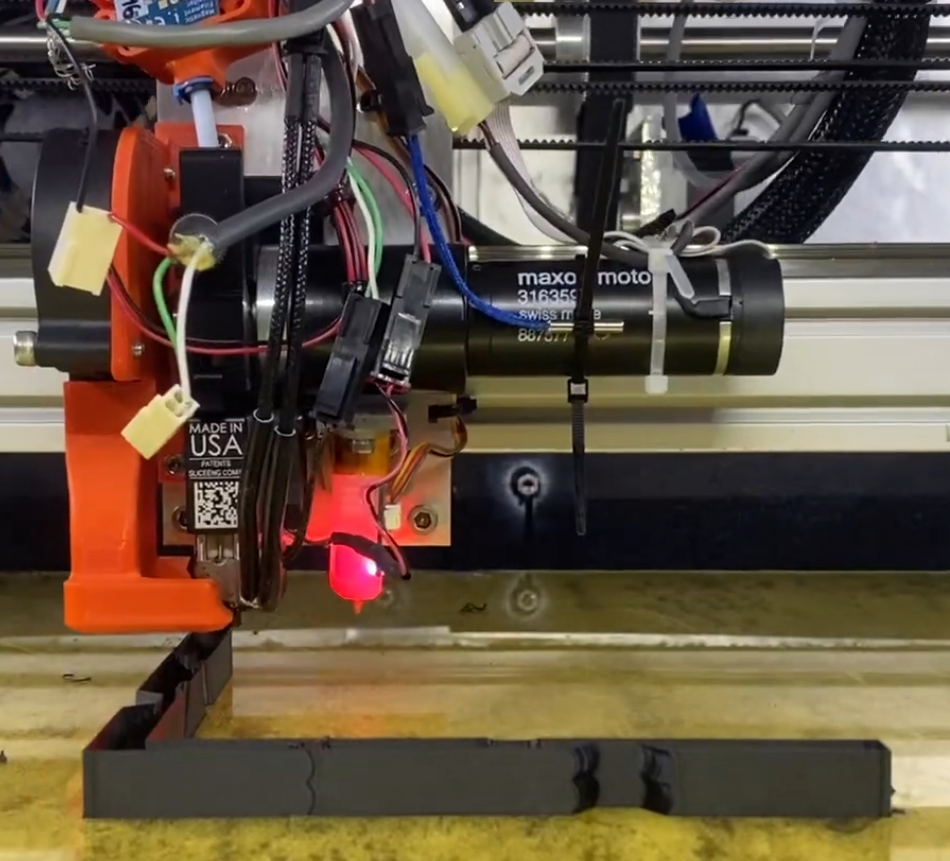
https://www.youtube.com/watch?v=UWuSsYKI-YMI've always been fairly happy with the print quality I get out of my two BMG extruders, however I've been impressed with the surface quality of prints done by my Stratasys Dimension BST 1200es (excluding 'ringing' artifacts on direction changes). Inspired by the DuePrint project posted here and on Hackaday, I pulled the extruder off the Stratasys printhead, and worked to get it integrated onto my DIY IDEX machine.
Prior to that though - about a year ago I started looking into designing my own extruder - inspired by all innovations of the LGX, Orbiter, Sherpa, etc. I was using these extremely slim Nema17 motors (PKP242D23A2) that are similar in stature to the popular pancake motors used on the newer generation of extruders (chief difference being the larger shaft diameter). As I played around with designs, it felt like I was reinventing the wheel - why not use a small stepper with an integrated gearbox (aside from price... right?). Starting looking at 15:1 Nema11 motors from Oriental Motor (PKP223D15A-CS15), but then the extruder project fell to the wayside. This past October I came across a nifty Nema8 with a 16:1 gearbox, and have been using that in a few different extruder combinations.
Based on the DuePrint project, I figured integrating the DC motor into the existing design would be easy enough - and after working past some Beta2 bugs, it was!

https://www.youtube.com/watch?v=vvajxcZIf6MUnfortunately, my lack of knowledge starts to creep in. With the Geckodrive G320x, I'm getting excessive motor thermal rise (at extreme conditions, the controller/encoder has either faulted out, or I disengaged the motor based on concerns of it failing) within 15 minutes or so. I'm seeing at least a 35°C thermal rise, and if my chamber sits at 62°C, that is not good. The twist is (detailed temperature measurements pending) that the Dimension series chamber temperatures settle at 75°C, and the motors operate comfortably at that temperature.
The Maxon P/N on the motor and gearhead don't lead anywhere (nor have I directly asked them, assume its 'proprietary' to Stratasys), but I'm pretty sure they're the similar to the following:
- RE 25 Motor - P/N 118743, 12V nominal voltage, 2.18ohm terminal resistance, 1.25A nominal current
- GP 32 Planetary Gearhead - P/N 166167, 86:1 (with the 8mm shaft option)
- 1000 CPT MR Encoder - P/N 225780
At slow speeds, I have to turn the current pot on the G320x to ~2.5A, and in normal printing conditions, I have to bring it closer to 4A. If I've identified a similar motor, that is much too high!
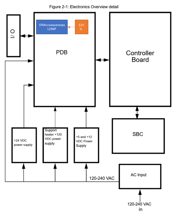
From the uPrint (very similar print head to the 1200es) service manual:
The 5 VDC and 12 VDC are used by the controller board, single board computer, and
hard drive. The 12 VDC also powers the filament motors.
• The 24 VDC powers the stepper motors, solenoids, fans, and chamber lights.
• The 120 VDC circuit powers the model heater and a separate 120 VDC supply powers
the support heater.
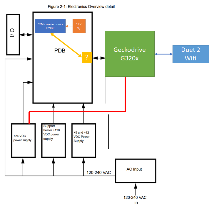
Block diagram of the uPrint/1200es - of note is the L298P Dual Full Bridge for the extruder motor.

This means then for the DuePrint implementation... we're using the G320x to signal to the PDB, and in turn the L298P?

Still doing some learning and digging around.
EDIT - Next Day Update:
Trying to use my brain here - my motor current estimates were based on how far I turned the current trimpot on the G320x (starting from 'off'). As one could expect, there is a bit of slop in the trimpot. For the setup with my DIY printer - Making the assumption that V.controller_in * I.controller_in = U.motor * I.motor, I finally hooked a meter in line with the motor controller input (24v supply). Testing at standstill (dithering) and slow 5mm/s feedrates, I'm sitting at roughly 24v * .4A = 9.6W. This took minuscule adjustments to the trimpot, closely monitoring the meter reading. I'm at a steady thermal condition, with ambient (chamber/bed is off) at 22°C, and the motor casement at 57°C (35°C rise, but may be wise to imagine the true range is 30°C - 40°C to include some error with the readings). Separate thermal testing inside the Stratasys is ongoing now. -
 undefined sebkritikel referenced this topic