Issues with pressure advance since RRF 3.4
-
I tried following slicers: Prusa Slicer, Super Slicer, Ideamaker and tried infill/perimeter overlap between 10% and 25%.
-
Think i have the same problem with corners.
My System :
Hardware:- Duet 3 6HC
- Duet 3 Tool Board 1LC
- Orbiter 2 Extruder
Firmware 3.4.3
SuperSlicer:
PA 0.2 on PETG

-
Tbh I'm not expecting a fix anymore. Too few are having issues and I understand that a problem that can't be reproduced is not fixable...
-
@argo I have it too
Mb6hc + 3hc + 1lc on Voron V2.4, Mini 5+ exp 2+ on Vzbot 235 AWD, Duet 2 wifi on Ox CNC and Mini 5+ on Millennium Milo v1.5 mini mill.
-
I think i found my problem
I used the wrong parameter.
SET_PRESSURE_ADVANCE ADVANCE=0.2M572 D0 S0.13
-
I‘m glad you fixed your problem.
-
@argo said in Issues with pressure advance since RRF 3.4:
Tbh I'm not expecting a fix anymore. Too few are having issues and I understand that a problem that can't be reproduced is not fixable...
It's true that it's not easy solving a problem that can't be reproduced, but we have not given up either.
-
What would be different in your environment to mine? I mean what if a Duet test machine does show the problem. Is there a debugging firmware involved that does provide more data?
-
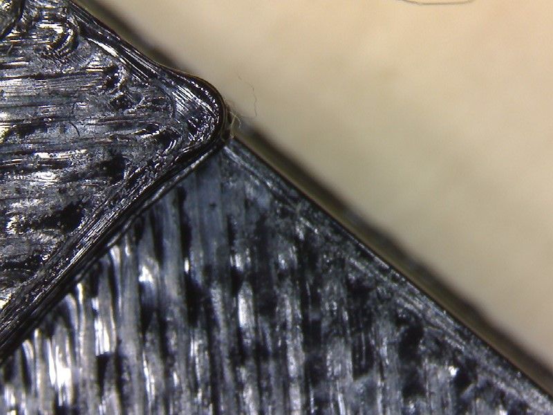
Same bulging here.
6HC + 1LC with RRF 3.4.3 and PA 0.035.
-
@r4ffers If you think you have this problem please post details of your configuration (mainboard, toolboard or expansion board if any, pressure advance setting, Input shaper setting, print speed, acceleration, jerk), plus if you can a photo showing an example of the problem.
-
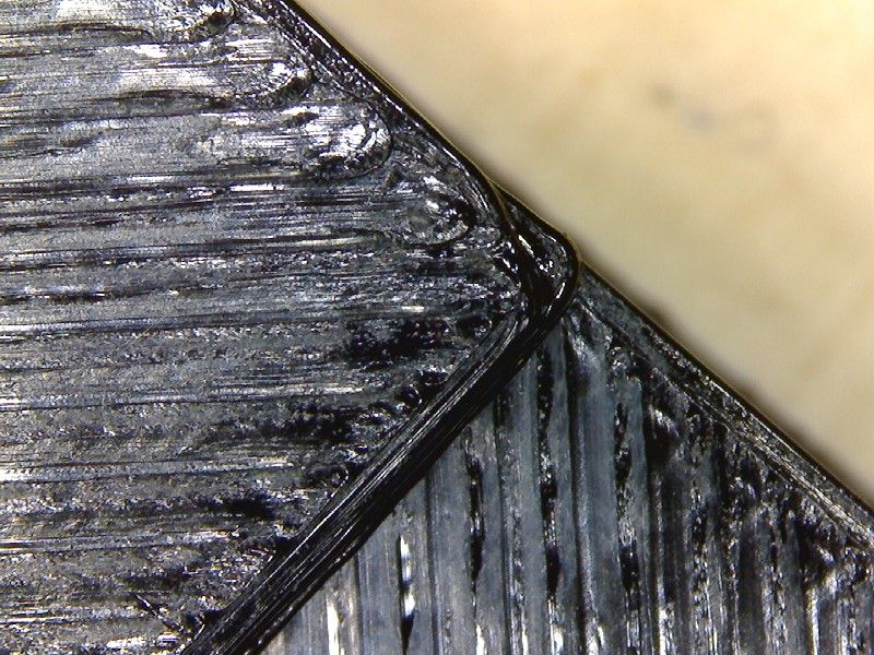
@gloomyandy Hi, here's some info.
Voron v2.4
Duet3 mini5+ with SBC
Duet3 mini2+ expansion board
Toolboard 1LC v1.2
LGX lite extruder
Firmware 3.4.3
PA 0.095Tried with superslicer & prusaslicer
Tried different speeds, accelerations & jerk settings giving same results.


Mb6hc + 3hc + 1lc on Voron V2.4, Mini 5+ exp 2+ on Vzbot 235 AWD, Duet 2 wifi on Ox CNC and Mini 5+ on Millennium Milo v1.5 mini mill.
-
@gloomyandy Here's my config file, Speed macro & prusaslicer gcode
1664142820911-bulgecheck.gcode; Configuration file for Duet 3 Mini 5+ (firmware version 3.3) ; executed by the firmware on start-up ; M550 P"duet3" ; ================================ ; PanelDue ; ================================ M575 P1 S1 B57600 ; ================================ ; Toolhead leds ; ================================ M150 X3 Q3000000 ;M150 B255 P255 S1 F1 M150 W255 P255 S2 F0 ; General preferences M111 S0 ; Debugging off G21 ; Work in millimetres G90 ; send absolute coordinates... M83 ; ...but relative extruder moves M669 K1 ; select CoreXY mode ; Limit axis M564 S1 H1 ; Forbid axis movements when not homed ; H1 Forbid movement of axes that have not been homed ; S1 Limit movement within axis boundaries ; Wait a moment for the CAN expansion boards to start G4 S2 ; ================================== ; DRIVERS ; ================================== M569 P121.0 S0 ; E - physical drive 121.0 goes backwards M569 P0.5 S1 D2 ; A -> Y - physical drive 0.0 goes forwards M569 P0.6 S1 D2 ; B -> X - physical drive 0.1 goes forwards M569 P0.0 S1 ; Z0 - physical drive 0.3 goes forwards M569 P0.1 S0 ; Z1 - physical drive 0.4 goes backwards M569 P0.2 S1 ; Z2 - physical drive 0.5 goes forwards M569 P0.3 S0 ; Z3 - physical drive 0.6 goes backwards M584 X0.6 Y0.5 Z0.0:0.1:0.2:0.3 E121.0 ; set drive mapping M350 X32 Y32 Z32 E16 I1 ; configure microstepping with interpolation M92 X160.00 Y160.00 Z800.00 E562.00 ; set steps per mm ; Accelerations and speed are set in separate macro M98 P"/macros/set_normal_speed.g" ; Stepper driver currents ; set motor currents (mA) and motor idle factor in per cent ; Drive currents M906 X1200 Y1200 Z1200 E600 I70 ; XYZ and E current M84 S120 ; Idle timeout ; ================================== ; Endstops ; ================================== ; Endstops M574 X2 S1 P"^121.io0.in" ; configure active-high endstop for high end on X via pin ^121.io0.in M574 Y2 S1 P"^0.io1.in" ; configure active-high endstop for high end on Y via pin ^io1.in M574 Z0 p"nil" ; No Z endstop ; Magnetic filament sensor ;M591 D0 P3 C"121.io1.in" S1 ; Axis travel limits ; Mind this is travel NOT print area M208 X0:350 Y0:360 Z-0.5:300 ; Set axis minima - negative X is to have 0,0 on bed corner ; WARNING on Z not to hit the roof - this is set here ; Belt Locations M671 X-60:-60:410:410 Y-10:420:420:-10 S20 ; Define Z belts locations (Front_Left, Back_Left, Back_Right, Front_Right) ; Position of the bed leadscrews.. 4 Coordinates ; Snn Maximum correction to apply to each leadscrew in mm (optional, default 1.0) ; S20 - 20 mm spacing M557 X50:300 Y40:325 P6 ; Define bed mesh grid (inductive probe, positions include the Y offset!) ; ================================== ; Bed heater ; ================================== M308 S0 A"Bed Heater" P"temp0" Y"thermistor" T100000 B3950 ; configure sensor 0 as thermistor on pin temp0 M950 H0 C"out0" Q10 T0 ; create bed heater output on out0 and map it to sensor 0 M307 H0 B0 R0.637 C222.4 D0.95 S1.00 V24.0 M140 H0 ; map heated bed to heater 0 M143 H0 S120 ; set temperature limit for heater 0 to 120C ; ================================== ; Hotend heater ; ================================== M308 S1 A"Nozzle" P"121.temp0" Y"pt1000" ; configure sensor 1 as pt1000 on pin 121.temp0 M950 H1 C"121.out0" T1 ; create nozzle heater output on 121.out0 and map it to sensor 1 M307 H1 B0 R2.518 C174.0 D6.14 S1.00 V23.8 M143 H1 S270 ; set temperature limit for heater 1 to 270C ; ================================== ; SENSORS MISC ; ================================== ; Define MCU sensors which will be available in DWC Extra View M308 S3 A"MCU" Y"mcu-temp" ; Officially NOT supported on Mini 3 5+ however seem to work M308 S4 A"Duet Drivers" Y"drivers" ; This is not really working as it is just a threshold crossing ; ================================== ; CHAMBER SENSOR ; ================================== M308 S10 A"Chamber" P"0.temp2" Y"thermistor" T100000 B3950 ; ================================== ; Z PROBES K0 (mag probe) and K1 (Microswitch Z0) ; ================================== ; MAG PROBE (GND, IO) ; ----------- ; This is the mag probe with microswitch in Afterburner M558 K0 P8 C"^121.io2.in" T18000 F600:180 H5 A10 S0.03 G31 K0 P500 X-2.5 Y24.5 Z0.86 ;Z ; Z-SWITCH ; ----------- ; This is the microswitch which is pressed by the Noozle M558 K1 P8 C"^io5.in" T18000 F1200:180 H3 A10 S0.005 R0 ; Omron micro switch G31 K1 P500 X0 Y0 Z0.47 ; Part cooling fan M950 F0 C"121.out1" ; create fan 0 on pin 121.out2 and set its frequency M106 P0 H-1 C"Part cooling fan" ; set fan 0 value. Thermostatic control is turned off ; Hotend fan M950 F1 C"121.out2" ; create fan 1 on pin 121.out1 and set its frequency M106 P1 S1 H1 T45 C"Hotend fan" ; set fan 1 value. Thermostatic control is turned on M950 F2 C"0.out4" ; create fan 2 on pin out4 and set its frequency M106 P2 S1 H3:4 T30 C"Controller fan 1" ; controlled by Sensor 3 - MCU ; Controller fan 2 M950 F3 C"0.out3" ; create fan 3 on pin out3 and set its frequency M106 P3 S1 H0 T60 C"Controller bay fan 2" ; Tools M563 P0 D0 H1 F0 ; define tool 0 G10 P0 X0 Y0 Z0 ; set tool 0 axis offsets G10 P0 R0 S0 ; set initial tool 0 active and standby temperatures to 0C M955 P121.0 I05 ; Input shaper M593 P"ei2" F48 ; Pressure advance M572 D0 S0.095 ; Calibration skew correction M556 S100 X0.542 ; Custom settings are not defined ; defines global variables M98 P"/macros/define_global_vars.g" ; Load override parameters M501 T0; Sets normal speeds and acceleration for printing operation M566 X300 Y300 Z240 E200 ; Set Jerk M203 X36000 Y36000 Z9600 E7200 ; Set maximum speeds (mm/min) M201 X10000 Y10000 Z700 E10000 ; Set maximum accelerations (mm/s^2) M204 P10000 T10000 ; Set printing acceleration and travel accelerationsMb6hc + 3hc + 1lc on Voron V2.4, Mini 5+ exp 2+ on Vzbot 235 AWD, Duet 2 wifi on Ox CNC and Mini 5+ on Millennium Milo v1.5 mini mill.
-
PA 0.095 is quite high for direct drive setup.
Do you also get incomplete infill lines if you increase PA further to get less bulging corners? -
@r4ffers One thing I would try if I were you would be to increase the E jerk a little, and drastically decrease the E acceleration. You never need that much E accel. It becomes completely pointless -- essentially no E acceleration is ever applied because there are not enough steps to interpolate speeds across.
Try E Jerk 500 and E Accel 2500.
*not actually a robot
-
@argo I've been messing around with it for the last week. I had it set at 0.055 previously. I have noticed zero change to PA when updated in config.g However I was tinkering earlier and when I change PA live using paneldue whilst printing it does have an effect. I got the corners not perfect but not too bad, updated config.g with new PA value. Ran the print again and back to crap corners again. It's almost like PA value in config.g is being ignored.
Mb6hc + 3hc + 1lc on Voron V2.4, Mini 5+ exp 2+ on Vzbot 235 AWD, Duet 2 wifi on Ox CNC and Mini 5+ on Millennium Milo v1.5 mini mill.
-
@r4ffers Make sure your slicer start gcode doesn't disable PA. Check every .g file on your SD card, too.
*not actually a robot
-
@bot thanks, I've just updated that. I'll try another print in a mo.
Mb6hc + 3hc + 1lc on Voron V2.4, Mini 5+ exp 2+ on Vzbot 235 AWD, Duet 2 wifi on Ox CNC and Mini 5+ on Millennium Milo v1.5 mini mill.
-
@bot ok good shout
-
@bot said in Issues with pressure advance since RRF 3.4:
@r4ffers Make sure your slicer start gcode doesn't disable PA. Check every .g file on your SD card, too.
Can't see anything tha'ts disabling PA.
if I issue M572 D0 whilst printing I get PA0.095 -
@argo said in Issues with pressure advance since RRF 3.4:
PA 0.095 is quite high for direct drive setup.
Do you also get incomplete infill lines if you increase PA further to get less bulging corners?Doesn't seem to be