I think i found my problem

I used the wrong parameter.
SET_PRESSURE_ADVANCE ADVANCE=0.2
M572 D0 S0.13
I think i found my problem

I used the wrong parameter.
SET_PRESSURE_ADVANCE ADVANCE=0.2
M572 D0 S0.13
I think i found my problem

I used the wrong parameter.
SET_PRESSURE_ADVANCE ADVANCE=0.2
M572 D0 S0.13
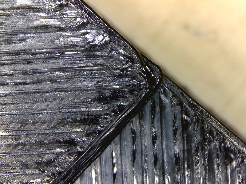
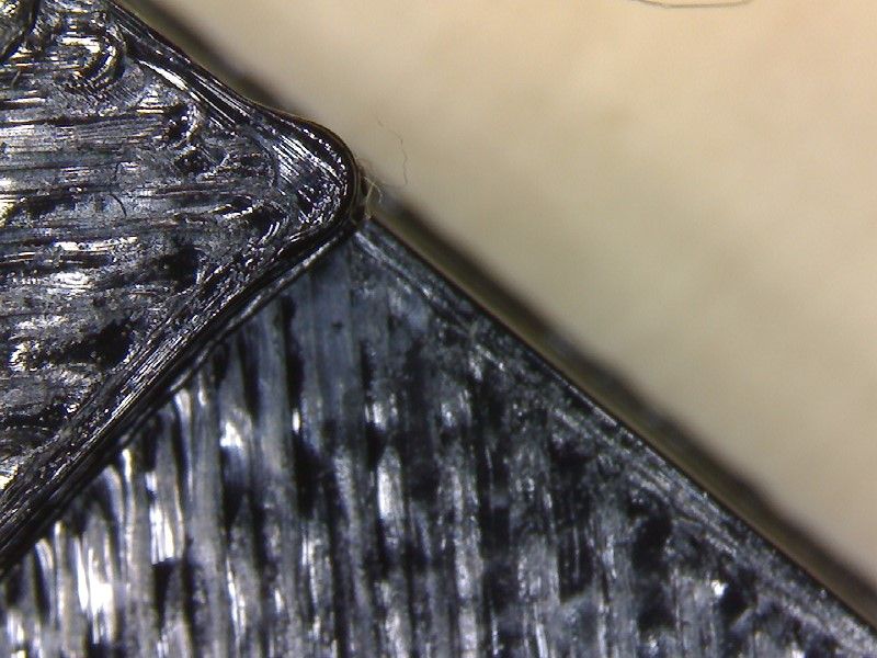
Think i have the same problem with corners.
My System :
Hardware:
Firmware 3.4.3
SuperSlicer:
PA 0.2 on PETG


Thank you for your help.
I increased the jerk value to 60 and the result is good now.
The tool is at the wrong position, without the tool offset. I assumed that the right way to correct it.
I first used an BL-touch, but ist had vibrations at higher speed, so i changed to an klicky probe.
I use a standard configuration for this printer, so i am not sure if the speeds are ok.
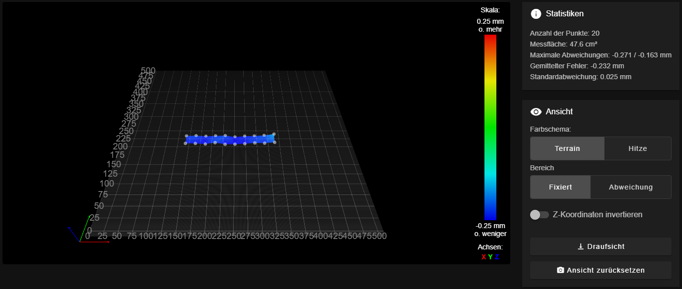
Bedmesh

config.g
G90                                     ; send absolute coordinates...
M83                                     ; ...but relative extruder moves
M550 P"V-Core 3"                        ; set printer name
M669 K1                                 ; CoreXY
G29 S1                                  ; Set Units to Millimeters
G4 S2 ; wait for expansion boards to start
M955 P121.0 I54
M593 P"mzv" F57.9
; Network
;M552 P0.0.0.0 S1                        ; enable network and acquire dynamic address via DHCP
M586 P0 S1                              ; enable HTTP
M586 P1 S0                              ; disable FTP
M586 P2 S0                              ; disable Telnet
; Drives
M569 P0.0 S1 D2 V10                         ; physical drive 0.0 goes forwards
M569 P0.1 S1 D2 V10                         ; physical drive 0.1 goes forwards
M569 P0.2 S1 D2 V10                         ; physical drive 0.2 goes forwards
M569 P0.5 S0 D2                        ; physical drive 0.3 goes forwards
M569 P0.4 S0 D2                         ; physical drive 0.4 goes forwards
M569 P121.0 S1 D2                         ; physical drive 0.5 goes forwards
M584 X0.4 Y0.5 Z0.0:0.1:0.2 E121.0        ; set drive mapping
M350 X16 Y16 Z16 E16 I1             	 ; configure microstepping with interpolation
M92 X80.00 Y80.00 Z800.00 E699.36            ; set steps per mm
M906 X1600 Y1600 Z1600 I30               ; set motor currents (mA) and motor idle factor in per cent
M906 E1200 I10
M207 S1.5 F7200 Z0.2
M84 S30                                 ; Set idle timeout

M566 X400.00 Y400.00 Z6.00 E300.00 P1          ; set maximum instantaneous speed changes (mm/min)
M203 X10800.00 Y10800.00 Z1000.00 E7200.00     ; set maximum speeds (mm/min)
M201 X3000.00 Y3000.00 Z100.00 E10000      ; set accelerations (mm/s^2)

; Axis Limits
M208 X0 Y-10 Z0 S1                               ; set axis minima
M208 X510 Y500 Z500 S0                         ; set axis maxima

; Endstops
M574 X1 S1 P"121.io1.in"                           ; configure active high endstops
M574 Y2 S1 P"io1.in"                           ; configure active high endstops

M671 X-4.5:250:504.5 Y0:505:0 S5       ; define positions of Z leadscrews or bed levelling screws
M557 X20:480 Y20:480 P5                        ; define 5x5 mesh grid

; Heaters
M308 S0 P"temp0" Y"thermistor" T100000 B3950 A"Bed"    ; configure sensor 0 as thermistor on pin temp0
M950 H0 C"out1" T0                                     ; create bed heater output on out5 and map it to sensor 0
M307 H0 B0 S1.00                                       ; disable bang-bang mode for the bed heater and set PWM limit
M140 H0                                                ; map heated bed to heater 0
M143 H0 S110                                           ; set temperature limit for heater 0 to 110C
M308 S1 P"121.temp1" Y"thermistor" T100000 B4267  A"Hotend" ; configure sensor 1 as thermistor on pin 121.temp0
M950 H1 C"121.out0" T1                           ; create nozzle heater output on 121.out0 and map it to sensor 1
M307 H1 B0 S1.00                                 ; disable bang-bang mode for heater  and set PWM limit
M143 H1 S280
M308 S1 H4
M308 S1 L-114
; set temperature limit for heater 1 to 280C
;; Run Heater PID Tune!!


M307 H1 R3.375 K0.385:0.000 D5.99 E1.35 S1.00 B0 V24.1
;; Run Bed PID Tune!! Bellow is an example for a 300x300 bed
M307 H0 R0.538 K0.254:0.000 D3.41 E1.35 S1.00 B0
; Fans
M950 F0 C"121.out1" Q500                   ; create fan 0 on pin out3 and set its frequency
M106 P0 C"Hotend Fan" S0 H1 T45 L255   ; set fan 0 name and value. Thermostatic control turned on for Hotend
M950 F1 C"121.out2" Q500                   ; create fan 1 on pin out4 and set its frequency
M106 P1 C"Layer Fan" S0 H-1 L255       ; set fan 1 name and value. Thermostatic control is turned off

; Tools
M563 P0 D0 H1 F1           ; define tool 0
G10 P0 X-4 Y-4 Z0            ; set tool 0 axis offsets
G10 P0 R0 S0               ; set initial tool 0 active and standby temperatures to 0C


; EVA 2 / BMG / E3D V6
; Z-Probe
;M950 S0 C"121.io0.out"                       ; create servo pin 0 for BLTouch
M558 P5 C"io2.out" H2 F100:55 R0.2 T10800 A5         ; set Z probe type to bltouch and the dive height + speeds
G31 P500 X-31 Y-22 Z2.75   ; set Z probe trigger value, offset and trigger height
M557 X15:490 Y15:460 S23                     ; define mesh grid
;; Inductive Probe
; M558 P5 C"!io3.in" H5 F400 T5000       ; set Z probe type to unmodulated and the dive height + speeds
; G31 P500 X-30 Y-15 Z0.20               ; set Z probe trigger value, offset and trigger height, more Z means closer to the bed
;; BLTouch
; M950 S0 C"io7.out"                     ; Create a servo pin on io7
; M558 P9 C"io7.in" H5 F240 T10800 A5    ; set Z probe type to unmodulated and the dive height + speeds
; G31 P25 X-28.00 Y-13.00 Z0.90          ; set Z probe trigger value, offset and trigger height, more Z means closer to the bed
M207 S1.5 F7200 Z0.2
T0
;M556 S300 X2.16
M98 P"macros/startup/set_globals.g"
Hi,
i am new to Duet, and the printer which i want to use is also new to me ( corexy )
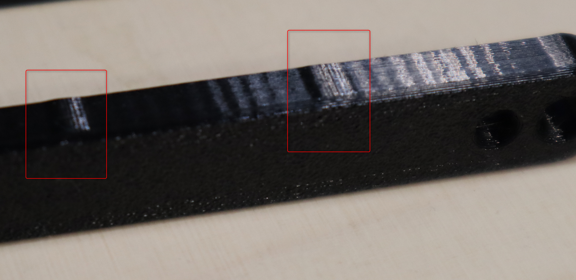
I get a strange resulst, when i try to print just a straight line, as you can see in the picture.

Video with G29 S1
Video with G29 S2
Hardware:
Duet 3 Main Board 6HC with raspberry pi
Duet 3 Tool Board 1LC
Does anyone got a hint, what could cause this problem ?
What i expect, at a moment with G29 S1 like G29 S2