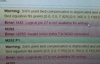
Error M280 Servo 7 Error M42 Logical Pin 27
-
We moved and cleaned or Modix Big 60 and we are not sure if a wire broke, came unplugged, or possibly got unplugged and possibly plugged back into the wrong location. When we run our Tilt Calibration + Bed Compensation it comes back with the 2 errors
Error M280 Invalid Servo Index 7
ErrorM42 Logical Pin 27 is not available for writing
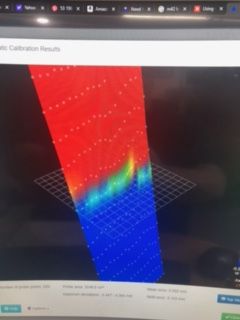
and our Height map come back vertical.

We are running Duet wifi and Duex 5Firmware Name: RepRapFirmware for Duet 2 WiFi/Ethernet
Firmware Electronics: Duet WiFi 1.02 or later + DueX5
Firmware Version: 2.05 (2019-12-13b1)
WiFi Server Version: 1.23
Web Interface Version: 1.22.6Here is the Config G, but we did no updates or changes to this, just the moving and cleaning and it had been working fine for months before this
;Generated by Modix - 1.3
;Modix Big-60, Dual Printhead
; General preferencesG90 ; Send absolute coordinates...
M83 ; ...but relative extruder moves; Network
M550 P"Big-60" ; Set machine name
;M551 P"my-password" ; Set password (optional)
M552 S1 ; Enable network
M586 P0 S1 ; Enable HTTP
M586 P1 S0 ; Disable FTP
M586 P2 S0 ; Disable Telnet; Drives
M569 P0 S1 ; Physical drive 0 goes forwards. X-Axis.
M569 P3 S1 ; Physical drive 3 goes forwards. E0-Extruder.
M569 P4 S0 ; Physical drive 4 goes backwards. E1-Extruder.
; DUEX5 BOARD
M569 P5 S0 ; Physical drive 5 . Y-Axis
M569 P6 S0 ; Physical drive 6 . Z LEFT REAR.
M569 P7 S0 ; Physical drive 7 . Z LEFT FRONT
M569 P8 S0 ; Physical drive 8 . Z RIGHT FRONT
M569 P9 S0 ; Physical drive 9 . Z RIGHT REAR
;
M584 X0 Y5 Z6:7:8:9 E3:4
M671 X-10:580:-10;580 Y580:-10:-10:580 S10
;
M350 X16 Y16 Z16 E16 I1 ; Configure microstepping with interpolation
M92 X100.00 Y100.00 Z2000.00 E686:700 ; Set steps per mm
M566 X300 Y500 Z100.00 E120.00 ; Set maximum instantaneous speed changes (mm/min)
M203 X18000.00 Y18000.00 Z300.00 E1200.00 ; Set maximum speeds (mm/min)
M201 X1000 Y1000 Z100.00 E250.00 ; Set accelerations (mm/s^2)
M204 P500 T1000 ; Set print and travel accelerations (mm/s^2)
M906 X1800 Y1800.00 Z2400.00 E800:800 I40 ; Set motor currents (mA) and motor idle factor in per cent
M84 S40 ; Set idle timeout; Axis Limits
M208 X0 Y0 Z-0.05 S1 ; Set axis minima
M208 X600 Y580 Z649 S0 ; Set axis maxima; Endstops
M574 X1 Y2 S1 ; Set active low and disabled endstops; Z-Probe
M574 Z2 S2 ; Set endstops controlled by probe
M307 H3 A-1 C-1 D-1 ; Disable heater on PWM channel for BLTouch
M558 P9 H5 F120 T6000 A1 R0.7 ; Set Z probe type to bltouch and the dive height + speeds
G31 P500 X-30 Y0 Z1.03 ; Set Z probe trigger value, offset and trigger height(Z-Offset) **** Z height change + 0.29 ****
M557 X0:560 Y0:580 S35:36.25 ; Define mesh grid. 100 Points
M376 H10 ; Height (mm) over which to taper off the bed compensation; Heaters
;E0:_________________________________________________
M305 P0 T100000 ; Set thermistor + ADC parameters for bed heat
M140 S55 R0 ; bed heater on
M143 H0 S125 ; set the maximum bed temperature to 125C
M307 H0 ; report the process parameters for heater 0;E1:_________________________________________________
M305 P1 X200 ; Set thermistor + ADC parameters for heater 1
M143 H1 S450 ; Set temperature limit for heater 1 to 450C
M307 H1 A# C# D# V# S0.25 B0 ; PID calibration;E2:________________________________________________
M305 P2 X201 ; Set thermistor + ADC parameters for heater 2
M143 H2 S450 ; Set temperature limit for heater 2 to 450C
M307 H2 A# C# D# V# S0.25 B0 ; PID calibration;E4: _______________________________________________
M141 H5 ; Heater H5 is the Chamber Heater
M143 H5 S120 ; Set max chamber temp to 120c
M305 S"Chamber temp" P5 T100000 B4267 C0 ; heater 5 is monitored by a 100K thermistor with B=3988
M307 H5 ; report the process parameters for heater 5; Fans
M106 P0 S0 I0 F500 H-1 ; Set fan 0 value, PWM signal inversion and frequency. Thermostatic control is turned off
M106 P1 S0 I0 F500 H-1 ; Set fan 1 value, PWM signal inversion and frequency. Thermostatic control is turned off
M106 P2 I-1 ;LED
M106 P3 S1 ; Set fan 3 value for bed relay to on; Tools
M563 P0 S"E0 Main" D0 H1 F0 ; Define tool 0
G10 P0 X0 Y0 Z0 ; Set tool 0 axis offsets
G10 P0 R0 S210 ; Set initial tool 0 active and standby temperatures to 0C
M563 P1 S"E1 Support" D1 H2 F1 ; Define tool 1
G10 P1 X0 Y65 Z0 ; Set tool 1 axis offsets Y-2 moves filament 2mm to back of machine X-1 moves filament 1mm to the right
G10 P1 R0 S210 ; Set initial tool 1 active and standby temperatures to 0C; Automatic power saving
M911 S21 R29.0 P"M913 X0 Y0 G91 M83 G1 Z3 E-5 F1000" ; Set voltage thresholds and actions to run on power loss. Power Failure Pause; Custom settings
;M564 H0 S0 ; Negative movements are allowed
G29 S1 ; Load the height map from file and activate bed compensation
M915 P1 S4 H400 F1 R2 ; Stall detection. For Y motor. Set to run rehome.g
M591 D0 P1 C3 S1 ; Regular filament sensor for E0
M591 D1 P1 C4 S1 ; Regular filament sensor for E1
;M581 E2 S1 T0 C0 ; Optional external switch for emergency stop
;M593 F40 ; Cancel ringing at 40Hz
;M592 D0 A0.01 B0.0005 L0.25 ;The amount of extrusion requested is multiplied by (1 + min(L, Av + Bv^2)) where v is the requested extrusion speed (calculated from the actual speed at which the move will take place) in mm/sec.
;M592 D1 A0.01 B0.0005 L0.25 ;The amount of extrusion requested is multiplied by (1 + min(L, Av + Bv^2)) where v is the requested extrusion speed (calculated from the actual speed at which the move will take place) in mm/sec.
M501Any thoughts on what the problem might be?
Thank you -
@sculpt-fabricator it sounds to me that you have an incorrect deployprobe.g or retractprobe.g file. Please post the contents of those files.
What type of Z probe does your machine have, and which pins on the Duet is it connected to?
-
@dc42 ; deployprobe.g
; called to deploy a physical Z probe
M280 P3 S10 ; deploy BLTouch; retractprobe.g
; called to retract a physical Z probe
M280 P3 S90 ; retract BLTouchBL touch is on PWM1 on the Duex 5 board
-
@sculpt-fabricator said in Error M280 Servo 7 Error M42 Logical Pin 27:
When we run our Tilt Calibration + Bed Compensation it comes back with the 2 errors
Can you post those macros?
And your BLTouch works otherwise for homing?
-
@phaedrux The BL touch works for homing , this is the one for the tilt / bed
M98 P"bed.g"
; bed.g
; called to perform automatic bed compensation via G32M300 S555 P666 ;
M291 S3 P"Press OK to continue, or CANCEL to abort"
M280 P7 S60
M300 S1888 P444 ; Beep
M561 ; clear any bed transform
G28 ; home
M42 P27 S255 ; Main LED on
M558 P9 H15 F120 T9000 A1 R0.7 ; Set Z probe type to bltouch and the dive height + speeds
G30
G30 P0 X0 Y0 Z-99999 ; probe near a leadscrew
G30 P1 X0 Y560 Z-99999 ; probe near a leadscrew
G30 P2 X560 Y570 Z-99999 ; probe near a leadscrew
G30 P3 X560 Y0 Z-99999 S4 ; probe near a leadscrew
G30 P5 X280 Y285 Z-99999 ; probe center of bed
G30
M400
M300 S1111 P444 ; Beep
M558 P9 H5 F120 T9000 A1 R0.7
M291 S3 R"BED MAPPING" P"The printer will now generate a new mesh map of the bed"
G29 S0 ; probe the bed and enable compensation
M42 P27 S0 ; Main LED off
M300 S888 P888
G4 P999
M42 P27 S255 ; Main LED on
M300 S888 P888
G4 P999
M42 P27 S0 ; Main LED off
M300 S888 P888
G4 P999
M42 P27 S200 ; Main LED on
M300 S1600 P555
M291 S2 P"Don't forget loading the mesh before each print (or insert M375 to starting script and M561 to ending script)" -
@sculpt-fabricator said in Error M280 Servo 7 Error M42 Logical Pin 27:
M280 P7 S60
At some point your Bltouch may have been using heater pin 7? Or at least that's what that macro is set to use.
@sculpt-fabricator said in Error M280 Servo 7 Error M42 Logical Pin 27:
M42 P27 S255 ; Main LED on
LEDs?
-
@phaedrux We figured out that after moving it somehow the bed was to far out to out for the auto tilt to work, so we had to do a manual adjustment , fixed the bl touch code in that bed.g and led, that was in the code we had copied when set up the auto tilt that would flash when done. Thanks for your help
-
 undefined Phaedrux marked this topic as a question
-
 undefined Phaedrux has marked this topic as solved