Toolboard Issues Galore
-
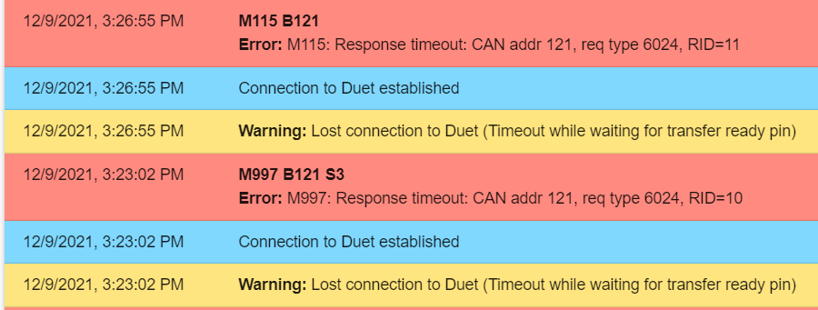
Here are the errors the OP posted over on the RatRig discord if they help. Looks like wiring issue to me if they could post how the toolboard is wired that would be great. Is it possible they are not using the resistor on the board?

-
@nurgelrot Thank you! Posting pics now.
-
Here is a Drive folder with some images.
-
 undefined Phaedrux marked this topic as a question
-
@arcadekilla @Nurgelrot @dc42 I have now disconnected my wiring and directly connected the board to the RJ11 connector. Still, the same 2 and 4 blinks of the red LED. Seems to be a firmware issue. Any help is very appreciated. My entire project is being held up by this issue. No idea what the solution would be.
-
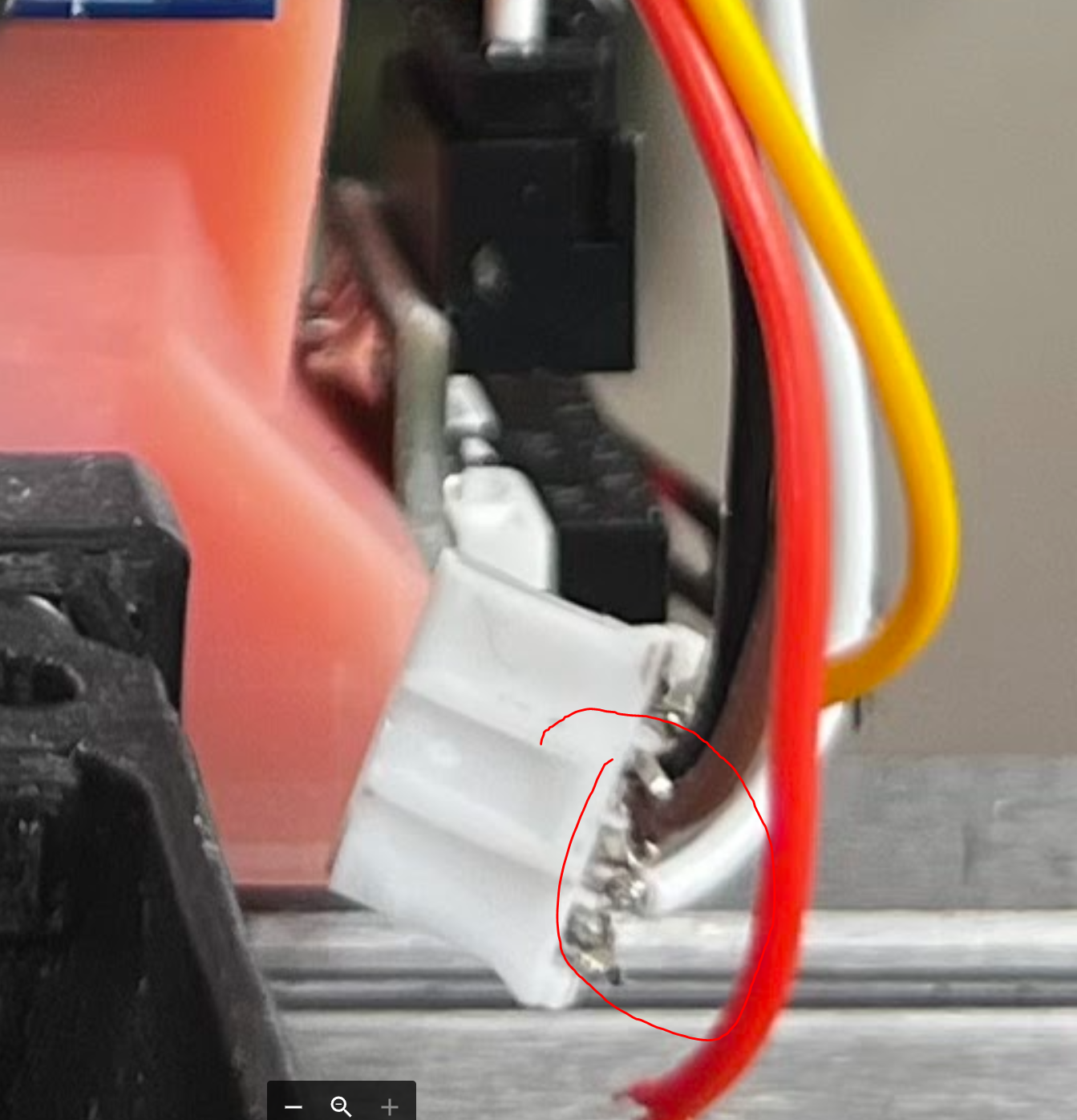
Are these connecters touching each other ?
-
Unplugged because of that fear. I don’t have a nice, small crimp tool so those are going to be redone. Same issues with nothing plugged in but CAN and power.
-
@arcadekilla @dc42 @T3P3Tony Any help on this? Currently holding my entire project up and seems to just be a firmware issue. I really don't want to spend $200 on an Atmel ICE just to try to get my Toolboard working.
 Kinda a bummer so far.
 -
@dc42 said in Toolboard Issues Galore:
@arcadekilla most like there is a problem with the CAN connection. Please provide photos showing the CAN connection between the 6HC and the tool board.
-
@t3p3tony I added a new photo to the Google Drive I linked above: https://drive.google.com/drive/folders/1-VVO-xWKIqfXKgMzeZSEM_xptEBvgdBy
I cut out my existing wiring and directly attached it to the RJ11 screw terminals directly. I have the solder bridge resistor in play and the other two wires are linked.
-
@arcadekilla you show a joiner on the effective CAN out with the white and yellow wires but the bus needs to be terminated with a 120 ohm resistor unless you have soldered the jumper on the back of the tool board. For something that has been around a while now and people have been using, it is a pretty big claim stating that it is a firmware bug.
-
@arcadekilla said in Toolboard Issues Galore:
and the other two wires are linked.
The other two wires should NOT be linked - the are the "through" connection to any other CAN boards; shorting those shorts the entire bus!
They should be either to a terminating resistor, or if you use one on the board, just unconnected.
-
@samlogan87 @rjenkinsgb The only reason I claimed a firmware bug is my Toolboard is blinking 4 and 2 which indicates a firmware issue. I have the resistor bridge soldered. I will report back ASAP with the bridge cables not connected. For some reason, I got to the conclusion that the resister was simply adding to the circuit of the bridged wires, not completing the circuit without them. I really appreciate the clarification. If this works, I owe @rjenkinsgb a few beers.
-
@rjenkinsgb I took the jumper off. I have tested this before and got a weird reboot loop from the main board. The same thing is happening but I successfully pinged the board before the reboot happens. That almost sounds like resistor-less behavior. Going to check my solder bridge.
-
@rjenkinsgb @samlogan87 The resistor solder bridge is fine. Damn...
-
Try resetting the tool board again, now the bus is connected?
-
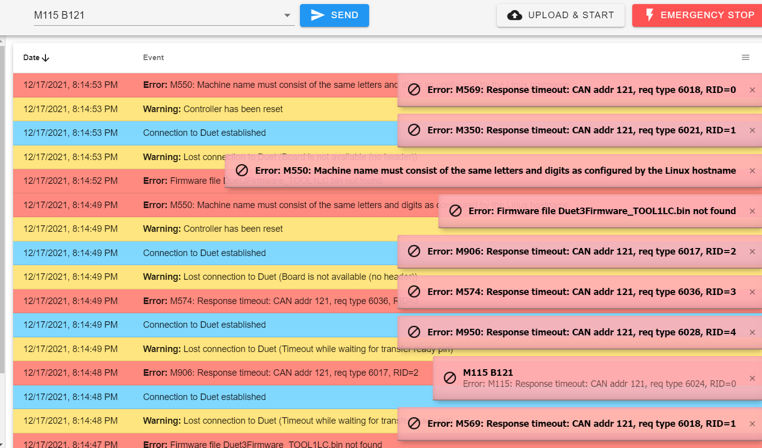
Still doing this reboot loop. Now the M115 command does not recognize the board.
-
@rjenkinsgb OMFG. I just re did a all of the Duet firmware and now it's working! WOOHOO! THANK YOU GUYS!
-
@arcadekilla I'm glad you got this working. I'll mark this as solved.
-
 undefined dc42 has marked this topic as solved

