An "hardware" advice for linear rails
-
Can I ask what the second rail is achieving?
If they are decent carriages and rails, it doesn't stiffen the system any more than a non-connected section of steel would do - i.e. bolt the rail on and leave the carriage off it will be just as effective for stiffness.
You have removed some moment from the first carriage (now the cantilever moment due to offset of the head from the rail is carried in push-pull between two rails, previously it was a fixed-end moment) but the single carriage alone was only at about 10% of its moment capacity (or would be if it was actually HiWin) by my reckoning:
Hiwin data is in https://www.hiwin.com/pdf/linear_guideways.pdf and particularly page 89 of the file, which has loading data:
MGN12H has a load rating 5.88 kN - about 600 kg - so the direct load is not significant fraction of the capacity.
More relevantly, M.R is 38.22 N.m. You are imposing 0.7 x 9.81 x 0.025 = 0.171 N.m (I'm guessing a 25mm offset from CoG to rail effective position). So you're at under 1% of the supposed static moment capacity in that direction.
This doesn't take into account inertial loading when you accelerate the head along the rail. However, suppose you allow 1g acceleration horizontally, the M.P value will also be 0.17 Nm (if the propelling belt aligns with the rail), or still under 1% of capacity.
It doesn't include drag from filament, cables etc. but I'm assuming they will be no more than similar to the weight forces.
Nor does it include factors of safety. Hiwin suggest FoS up to 5 (see page 6) even with impact. So applying that you're at about 5% of capacity in each of the two principal moments. Even if their effects sum directly, you're at about 10% of capacity.
So yes, converting that moment to a push-pull on two (if you can make them share load and not fight each other) will reduce the utilisation, from about 10% to about 5% (I think the first carriage will still be carrying the X-acceleration moment). Getting two rails to cooperate seems quite a lot of work to move from ten-times-stronger-than-it-needs-to-be to twenty-times-stronger.
It would probably help if the rails are so poor your carrages have slop under moment loading, but then buying one good rail might be a better option than two poor ones.
-
@fcwilt said in An "hardware" advice for linear rails:
Does that apply if he is happy with the X2 and wants to use it?
Not at all. Just that sometimes rethinking a design means really rethinking it.
-
@thedragonlord said in An "hardware" advice for linear rails:
@phaedrux said in An "hardware" advice for linear rails:
@thedragonlord said in An "hardware" advice for linear rails:
@zapta said in An "hardware" advice for linear rails:
@thedragonlord said in An "hardware" advice for linear rails:
It's impossible, the X2 is a single piece
You can also rethink the x2 choice.

no, I've already bought it

I'm not English so maybe I don't understand your humor....I was just asking for advices....
No humor. Just saying to consider all options.
-
@achrn said in An "hardware" advice for linear rails:
Can I ask what the second rail is achieving?
If they are decent carriages and rails, it doesn't stiffen the system any more than a non-connected section of steel would do - i.e. bolt the rail on and leave the carriage off it will be just as effective for stiffness.
You have removed some moment from the first carriage (now the cantilever moment due to offset of the head from the rail is carried in push-pull between two rails, previously it was a fixed-end moment) but the single carriage alone was only at about 10% of its moment capacity (or would be if it was actually HiWin) by my reckoning:
Hiwin data is in https://www.hiwin.com/pdf/linear_guideways.pdf and particularly page 89 of the file, which has loading data:
MGN12H has a load rating 5.88 kN - about 600 kg - so the direct load is not significant fraction of the capacity.
More relevantly, M.R is 38.22 N.m. You are imposing 0.7 x 9.81 x 0.025 = 0.171 N.m (I'm guessing a 25mm offset from CoG to rail effective position). So you're at under 1% of the supposed static moment capacity in that direction.
This doesn't take into account inertial loading when you accelerate the head along the rail. However, suppose you allow 1g acceleration horizontally, the M.P value will also be 0.17 Nm (if the propelling belt aligns with the rail), or still under 1% of capacity.
It doesn't include drag from filament, cables etc. but I'm assuming they will be no more than similar to the weight forces.
Nor does it include factors of safety. Hiwin suggest FoS up to 5 (see page 6) even with impact. So applying that you're at about 5% of capacity in each of the two principal moments. Even if their effects sum directly, you're at about 10% of capacity.
So yes, converting that moment to a push-pull on two (if you can make them share load and not fight each other) will reduce the utilisation, from about 10% to about 5% (I think the first carriage will still be carrying the X-acceleration moment). Getting two rails to cooperate seems quite a lot of work to move from ten-times-stronger-than-it-needs-to-be to twenty-times-stronger.
It would probably help if the rails are so poor your carrages have slop under moment loading, but then buying one good rail might be a better option than two poor ones.
Thanks for your scientific approach! I perfectly understood what you said. My rails aren't comparable to HiWin, they are cheap chinese ones bought on Amazon but I've already had them in my own. The cost of a single HiWin is higher than X2 cost so for now I've preferred to buy the X2, try to make it work with the rails I own...in future I'll see...I've thought mounting the opposite rail mainly not for the stiffness but to reduce as much as I can the oscillation during the direction change and along the travels in Y. Of course, as is absolutely obviuos, I'm not an engeneer and maybe I'm saying (and doing) a lot of bul@@@@its...on the other hand I always like to learn new thing, to assemble, reassemble and try add new features in my printer not only to make it print better but because I like manual working and learning....so thanks to everybody for the precious help, I really appreciated all the advices you gave me based on scientific facts...when the 10mm belts and pulleys will arrive I'll assemble the whole and I'll let you know the result....
-
@thedragonlord said in An "hardware" advice for linear rails:
I've thought mounting the opposite rail mainly not for the stiffness but to reduce as much as I can the oscillation during the direction change and along the travels in Y.
(Assuming Y motion means movement perpendicular to the 2020, ie where the whole gantry moves, not the head moving along the gantry:)
I didn't include the moment arising from that when considering the effects on the carriage because it looked to me like your head CoG is near to the level of the 2020. That is, the vertical offset between the centre of mass (and therefore the point where the inertia forces will act, effectively) and the axis of the 2020 looks quite small. As such, there is little moment on the carriage arising due to those accelerations.
The interia forces will cause the 2020 to flex, however, and I agree that the rail will stiffen against that. It will also balance (and cancel) any bimetallic curvature (which was mentioned in the thread), if you are changing the temperatures around the gantry enough for that to be significant.
-
@achrn said in An "hardware" advice for linear rails:
@thedragonlord said in An "hardware" advice for linear rails:
I've thought mounting the opposite rail mainly not for the stiffness but to reduce as much as I can the oscillation during the direction change and along the travels in Y.
(Assuming Y motion means movement perpendicular to the 2020, ie where the whole gantry moves, not the head moving along the gantry:)
I didn't include the moment arising from that when considering the effects on the carriage because it looked to me like your head CoG is near to the level of the 2020. That is, the vertical offset between the centre of mass (and therefore the point where the inertia forces will act, effectively) and the axis of the 2020 looks quite small. As such, there is little moment on the carriage arising due to those accelerations.
The interia forces will cause the 2020 to flex, however, and I agree that the rail will stiffen against that. It will also balance (and cancel) any bimetallic curvature (which was mentioned in the thread), if you are changing the temperatures around the gantry enough for that to be significant.
so in your opinion the second rail is almost unuseful in my configuration if I understood well, right?
-
@thedragonlord said in An "hardware" advice for linear rails:
so in your opinion the second rail is almost unuseful in my configuration if I understood well, right?
I don't think it's an easy yes / no.
I don't think it's necesary.
It will have some minor benefits, but I don't think they are large (if your rails are reasonable ones).
If you can make the gantry run smoothly (i.e. no binding or stiffening of the carriages) it won't do any harm.Personally, I'd use a larger section (2040 or a hollow box) as the gantry rather than double up the rails. For a 500mm span gantry I would probably go larger than 2020, but I haven't built a printer with a traveling gantry so I'm going by theory not practical experience.
-
@achrn said in An "hardware" advice for linear rails:
Personally, I'd use a larger section (2040 or a hollow box) as the gantry rather than double up the rails. For a 500mm span gantry I would probably go larger than 2020, but I haven't built a printer with a traveling gantry so I'm going by theory not practical experience.
Interesting. When you criticised my post about the value of using maths to calculate beam deflection, you said quote" ....... I remain of the opinion that my estimate of 0.03mm is closer to reality......." So you think that 0.03mm beam deflection is unacceptable despite never having build a printer a printer with a travelling gantry. If you consider 0.03mm deflection to be unacceptable, what would you consider to be acceptable? Just curious.
-
@achrn said in An "hardware" advice for linear rails:
@thedragonlord said in An "hardware" advice for linear rails:
so in your opinion the second rail is almost unuseful in my configuration if I understood well, right?
I don't think it's an easy yes / no.
I don't think it's necesary.
It will have some minor benefits, but I don't think they are large (if your rails are reasonable ones).
If you can make the gantry run smoothly (i.e. no binding or stiffening of the carriages) it won't do any harm.Personally, I'd use a larger section (2040 or a hollow box) as the gantry rather than double up the rails. For a 500mm span gantry I would probably go larger than 2020, but I haven't built a printer with a traveling gantry so I'm going by theory not practical experience.
Thanks again! Just a last question....what's a hollow box?
-
@TheDragonLord Would it be an option to add a rail in front of the motors ?

-
@yveske said in An "hardware" advice for linear rails:
@TheDragonLord Would it be an option to add a rail in front of the motors ?

no, absolutely
-
@thedragonlord
Hi,
Could you send me a STEP file of the gray parts holding the pulleys?
There is a arrangement I want to try out and post here for you to look at.
Frederick
-
@fcwilt said in An "hardware" advice for linear rails:
@thedragonlord
Hi,
Could you send me a STEP file of the gray parts holding the pulleys?
There is a arrangement I want to try out and post here for you to look at.
Frederick
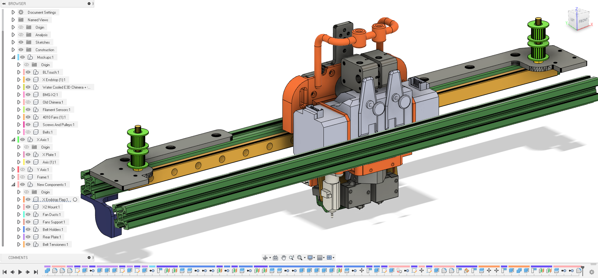
If you mean the flanges wich connect the X gantry to the Y linear rails I can't send the file because they're part I bought and the sellers sended me the STLs only for reference with the promise to not share them
-
@thedragonlord said in An "hardware" advice for linear rails:
If you mean the flanges wich connect the X gantry to the Y linear rails I can't send the file because they're part I bought and the sellers sended me the STLs only for reference with the promise to not share them.
Understood.
How many of what we see in the images are parts you bought?
Frederick
-
@fcwilt said in An "hardware" advice for linear rails:
@thedragonlord said in An "hardware" advice for linear rails:
If you mean the flanges wich connect the X gantry to the Y linear rails I can't send the file because they're part I bought and the sellers sended me the STLs only for reference with the promise to not share them.
Understood.
How many of what we see in the images are parts you bought?
Frederick
just the two flanges and the vertical plate wich connects to the rail cursor
-
@thedragonlord said in An "hardware" advice for linear rails:
just the two flanges and the vertical plate which connects to the rail cursor
It would be the part I wanted to modify. That seems to be the way of the universe.

Were they designed for you or were they part of another printer design?
Thanks.
Frederick
-
@fcwilt said in An "hardware" advice for linear rails:
@thedragonlord said in An "hardware" advice for linear rails:
just the two flanges and the vertical plate which connects to the rail cursor
It would be the part I wanted to modify. That seems to be the way of the universe.

Were they designed for you or were they part of another printer design?
Thanks.
Frederick
it's a kit for the Tronxy X5S
-
@thedragonlord said in An "hardware" advice for linear rails:
it's a kit for the Tronxy X5S
Thanks much. Maybe they have a doc showing the dimensions - I could work from that.
Frederick
-
@fcwilt said in An "hardware" advice for linear rails:
@thedragonlord said in An "hardware" advice for linear rails:
it's a kit for the Tronxy X5S
Thanks much. Maybe they have a doc showing the dimensions - I could work from that.
Frederick
the seller is DMaker. com
EDIT
dmaker.it not .com and the kit is named KIT V2 ECO -
@thedragonlord said in An "hardware" advice for linear rails:
Thanks again! Just a last question....what's a hollow box?
I mean a rectangular tubular member.
This is returning to a comment made up the thread - 2020 pultrusion (and similar) is good in lots of ways, but it's not the best from either a sructural strength or stiffness point of view.
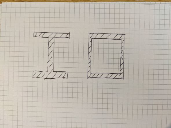
In general terms, for resting bending you want material spaced away from the centre of the section - so for bending in one direction only you end up with 'I' beams that have chunky flanges and tall narrow webs that are mainly just there to hold the flanges apart but acting together. If you have similar bending forces in both directions you want flanges in both directions, so you end up with a rectangular tube, or box.
The other big win for tubes / boxes is that closed hollow sections are much much better than 'open' sections in torsion. So of these two sections, if they had same quantity of material and the same dimensions, the one on the right (which is what I mean by hollow box) will be massively stiffer in torsion :

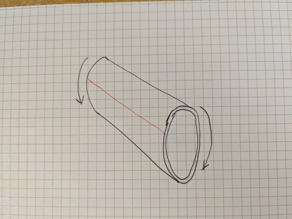
You can demonstrate this for yourself - if you take a cardboard tube from the middle of a roll of toilet tissue and try and twist it it's fairly strong, if you cut down its length so it's now a C-section and twist it it becomes much more flexible, because the cut edges shear along each other. That is like this: very stiff when the tube is intact, cut along the red line and it becomes very flexible:

Round tubes are particularly good in torsion, but are less good in bending (flexure) unless the bending is equal in any or all directions. Round tubes are also difficult to join to. Rectangular tubes are nearly as good in torsion, but easier to join (though not as easy as 2020). So when I said 'hollow box' I just meant a rectangular tube.
The 2020 sections do have a small hollow part in the middle, but it's not very big. That's why if you don't need the ease of connections, it might be better (but less convenient) to use a section that's more tailored to what you require (but you will need to drill holes for nuts and bolts, possibly use blind fixings etc). On balance, I'd probably stick with the 2020 range of sections, but (as previously noted) go up a size if worried about stiffness.