M906 motor current
-
@Runklestiltskin said in M906 motor current:
One has the glorious job to drive two drivers, the other two drivers wotk single motors.
Can you explain that a bit more? Maybe include a diagram of what you mean?
But as you say, M906 is per axis, not per motor.
https://duet3d.dozuki.com/Wiki/Gcode?revisionid=HEAD#Section_M906_Set_motor_currents
RepRapFirmware does not support individual motor settings where an axis has multiple motors connected to different stepper drivers. The first parameter specified will be used for all motors on the axis. You should use identical motors on any axis that has more than one motor to avoid unexpected behaviour.
-
What board are you using?
Are you saying that 2 steppers are wired to 1 driver and the third is wired to another?
-
@Phaedrux hi,
I am running a Duet 3 with two z motors on driver 3. One motor on driver 4 and one on driver 5. I tried to set different motor currrents, since driver 3 has to drive two motors. I stumbled upon the fact that the M906 sets motor current per axis instead of per driver, what would make way more sense to me. Is there a way to set different currents for one driver?
Thanks by the way.
-
@dhusolo I have 4 z steppers on the duet 3, due to the lack of a 7th driver, I wired one motor to driver 4, one to driver 5 and two to driver 3.
I am searching a way to define different currents for one axis in M906.
Thanks for the reply
-
@Runklestiltskin said in M906 motor current:
I am searching a way to define different currents for one axis in M906.
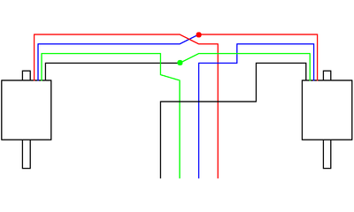
Sorry, that's not possible. If all four motors are the same, wire the pair that share a driver in series rather than in parallel, then the motors will all receive the same current.
Wiring diagram for wiring in series:

Though be aware that you need to connect the same phases together, and your stepper motor wiring may differ from the above. In the above, black/green are one phase, and red/blue are the other. To check the phases of your motors, see https://duet3d.dozuki.com/Wiki/Choosing_and_connecting_stepper_motors#Section_Identifying_the_stepper_motor_phasesIan
-
@droftarts For info, there is a "kind of" way to have different motor currents for multiple motors on the same axis (although in this case it won't be appropriate). The way to do it is create axes for each motor, set the current for each axis, then use M584 to "recombine" the motors to a single axis. DC tells me that that the motor currents will maintain their original assignments after they get re-mapped.
-
@deckingman said in M906 motor current:
DC tells me that that the motor currents will maintain their original assignments after they get re-mapped.
Maybe I did say that; however when the motors are switched between idle hold and active mode, or when you use M913, the current will be reset to the configured value for that axis. So it's only useful for making a temporary change prior to doing some specific moves, when you know that idle hold won't kick in.
-
I thank all of you for your answers.
Wouldn't it be better to define the motor current per driver for future firmware versions?
-
@dc42 said in M906 motor current:
@deckingman said in M906 motor current:
DC tells me that that the motor currents will maintain their original assignments after they get re-mapped.
Maybe I did say that; however when the motors are switched between idle hold and active mode, or when you use M913, the current will be reset to the configured value for that axis. So it's only useful for making a temporary change prior to doing some specific moves, when you know that idle hold won't kick in.
Ahh. You didn't explain that before - I wish you had. This came up some time back when I asked because my UV and gantry is much higher mass than my XY and AB gantries, so I changed the motors for higher current Nema 23s on those UV axes. That's when I asked the question about whether the current I set for UV would be retained when the A,B,U and V motors get re-mapped to XY and you simply said yes.
In light of what you now say, it seems that my UV axis has been running with 1800mA instead of the 2400 mA I thought it was set to. And the only way I can run 2400mA is to change the other four (2amp max) motors as well. That explains something but it's also a bu**er.
-
@deckingman rather than combining the U, V, A and B back to X and Y, you could just map them with the Kinematics parameters: https://duet3d.dozuki.com/Wiki/Gcode#Section_Parameters_for_Cartesian_CoreXY_CoreXZ_CoreXYU_CoreXYUV_MarkForged_kinematics_RRF_2_03_and_later_only
Then each axis can have its own motor settings.
Ian
-
@droftarts Maybe I already do and maybe I am confusing myself. So I have..................
M584 X3.2:0.0:0.2 Y3.1:0.1:0.3 Z3.0 U0.0 V0.1 A0.2 B0.3 E1.0:1.1:1.2:2.0:2.1:2.2 P7
and
M669 K8 A0:0:0:0:0:1:1 B0:0:0:0:0:1:-1; CoreXYUV plus AB force cancelling gantry
Then this
M906 X1800 Y1800 U2300 V2300 A1800 B1800 Z1800 E600:600:600:600:600:600 I20
So in that scenario, taking just the X axis motors, I have 3.2:0.0:0.2. But 0.0 is also U and 0.2 is also A.
So what is the motor current for driver 0.0? Is it 1800 as per the X axis, or is it 2300 as per the U axis?
Edit. And after all the axes have been homed, the P7 parameter in M584 gets changed to P3. Does that then affect/change the motor currents?
Edit 2. Sending M584 P3 then sending M906 reports the same motor currents as having M584 P7 so I guess that answers that question. It's just what is the motor current when a motor is assigned to 2 axes that remains.