Hollow shaft extruder
-
@CNCModeller Sorry I have been busy elsewhere and didn't see your questions.
I know you've bought bearings now but, for reference, here are some considerations for flanged bearings:
- OD of the part touching the filament needs to be about 9mm or less. i.e. that's the diameter of the flange or just the OD for any non-flanged bearings. Larger than 9mm and the bearings start interfering with each other.
- @rqthree uses extended-race bearings which helps with mounting on his machined carriers. I don't bother as I use printed carriers and it is easy to print a bezel on which the race mounts.
- It is possible to use a mix of different size bearings. My best extruder has two MF95ZZ bearings which have a 10mm flange. To avoid interference I use a smaller third bearing and mount the three of them slightly non-symmetrically around the filament axis. The slightly larger bearings have more grip.
- Depending on which country you're in, metric or imperial may be easier to source.
I, like @rqthree, have found a 0.1mm bite to be about perfect. More than that and it increases drag. Less than that and it both reduces thrust and also makes the tolerances much tighter, e.g. something like a 0.02mm error is a much bigger proportion of a 0.05mm bite than of 0.1mm.
There is nothing particularly special about 9.1mm. It's what I was targeting when I made my videos because it was about 0.1mm smaller than the diameter of the unground flange and I wanted to take off as little material as possible. Realistically, I could have gone for 9.15mm. My primary considerations for diameter are:
- Less grinding takes less time and effort and leaves fewer chances for machining errors.
- You can always take more off if necessary but you can't put it back on, so aim for larger and adjust to smaller if need be. e.g. if you want the same diameter for all the bearings and one accidentally ends up a bit smaller you can then make the others smaller too.
- I have found that larger diameters grip the filament better. I am guessing this is because the bite has a different shape with a bit more overlap.
- As @rqthree says, if you are printing your carrier then it's easier to make a custom carrier for whatever sizes you ended up grinding the bearings.
Drag on the filament is minimal as long as the bite is small enough. @rqthree initially designed a counter-torque mechanism into his extruder but later found it was not needed. The back-torque provided by the melted filament in the nozzle is sufficient. I benefited from this knowledge and have never even implemented a counter-torque. You do see a bit of backlash and it varies a bit by filament type. You may find retraction distances benefit from a bit of re-tuning. But I have not found it affects the print. Obviously consistent filament diameter becomes an important factor, but any decent filament these days has fine tolerances. It also helps if you minimise the path length through the hotend heatsink as this decreases the springiness of the filament section between the extruder and the nozzle.
Speed: there are a couple of guys on the CroXY Discord server who are exploring using VDE for high-speed. The simplicity and weight considerations are just too tempting. At high enough speeds VDE does under-extrude. There can also be issues with having to run the motor hotter which is problematic with the filament running through the shaft. More flanged bearings definitely help under-extrusion but they add drag and increase the likelihood of multiple grooves making a mess of each other. A mix of larger and smaller bearings mounted asymmetrically is also helpful. Firmware can help a bit as well, Marlin now has nonlinear extrusion and I think someone (@oliof maybe) said that RRF has has this feature for ages. Possibly Klipper does as well, I don't know. The guys at CroXY are, I think, experimenting with drilling a larger hole in the motor shaft and lining it with PTFE tubing. Mounting the motor on the hotend heatsink and sharing cooling air with the heatsink is also something to explore.
One idea I may go back to one day is a two bearing VDE. This required the filament path to be constrained by the walls of the hole leading up to the bearings, so adds friction, but it would allow for much larger bearings without any risk of interference.
@rqthree's observations about using PLA for a printed carrier match my experience. I have not experimented widely here but in my best round of testing I did swap from PETG to PLA when I noticed there was a difference.
-
Hi again,
we have discussed earlier to use pipe-cutter blades instead of flanged bearings.
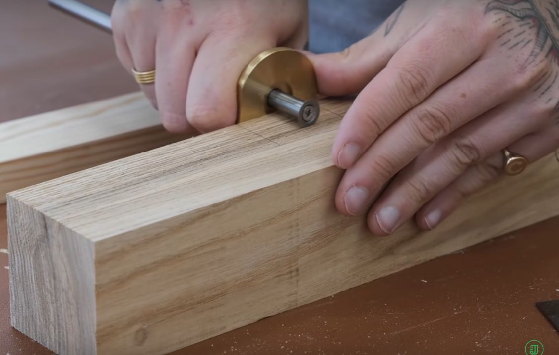
Now I've seen a woodworking video which shows an interesting tool. The blade is very small and replaceable, so there's a good chance we can buy it separately and use it for our purpose, too.
But I don't know the name of the tool. If anyone knows, pleas let me know.
-
@o_lampe Veritas Streichmaß or DICTUM Streichmaß and "veritas streichmaß ersatzmesser"
There is also one with assembled adjusting ring on https://www.feinewerkzeuge.de/veritas-marking-gauges.html, "VERITAS Schneidräder für Zapfen" but it's a bit expensive (22 EUR), but maybe one can DIY.
-
@JoergS5 Very interesting. The idea is to bulk-buy instead of DIY.
IMHO the biggest problem with Toms handmade bearings is to keep the diameter constant. -
Veritas tools are nice, but not cheap.
https://www.axminstertools.com/veritas-wheel-for-marking-gauges-477717 is a UK retailer.
The company is Canadian: https://www.veritastools.ca/en-ca/shop/tools/hand-tools/marking-and-measuring/marking-gauges/59455-veritas-standard-wheel-marking-gauge?item=05N3321 and the wheel is https://www.veritastools.ca/en-ca/shop/tools/hand-tools/marking-and-measuring/marking-accessories/102171-replacement-wheel-for-veritas-standard-wheel-marking-gauge?item=05N3511
-
@achrn Thanks for the links, but in the canadian closeup picture it looks horrible. I don't see, how it would rotate nicely.
-
@o_lampe I believe the entire shaft rotates, not just the cutter.
-
@Phaedrux Possible, but I checked the video again and he adjusts the shaft-depths and locks it with a thumbscrew.
So either it's a rotating shaft in a fixable tube, or the screwhead doesn't fully clamp the blade and acts as a bearing, too.
Both ways wouldn't be easy to adapt to a blade-extruder. -
On the Veritas tool, neither the cutter nor the shaft rotates during use. The cutter scribes the wood, and the shaft is rotated to a new cutter edge position when and if the cutter becomes dull.
The screw just holds the cutter firmly on the end of the shaft. The cutter is not supposed to rotate at all.
-
@rqthree So it's probably not 100% round, because it's not relevant for the actual usecase?
I think, we have to look elsewhere then. The blade extruder only has a commercial future, when we find a way to build it economically.
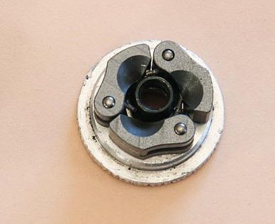
For the rotor body to be adjustable to the blade diameter, I thought of an arrangement like this:
Three individual bodies which are held together with an O-ring to provide adequate pressure.

[Picture curtesy of RC-network} -
No activity for quite a while, but if anyone is still interested, here's a source of carbide cutter wheels. The V500 looks of particular interest, and they can manufacture to spec:
https://www.fletcher-terry.com/frame-joining-cutting-hanging-automation-1/carbide-cutting-wheels
I'm still using my original ground flanged steel bearing from 3+ years ago, and all is well
-
@rqthree Nice find!
I started looking for a wood lathe and the turning tools I'd need and guess what I've found:
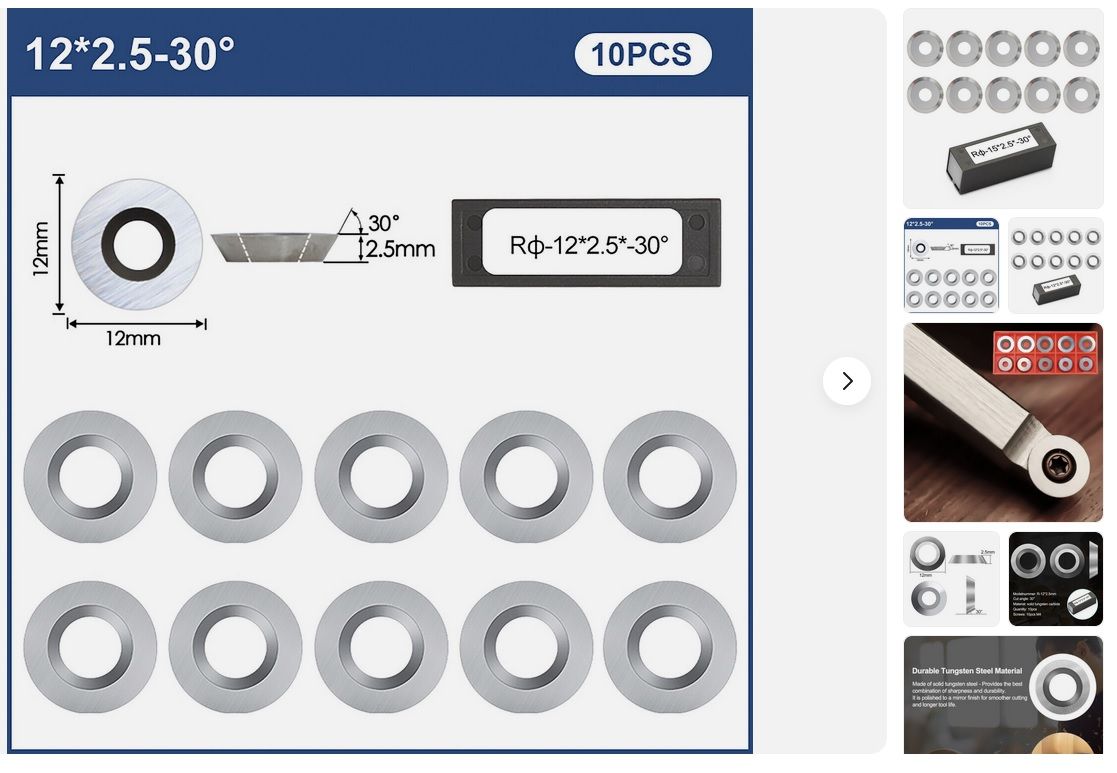
Wood turning Tungsten carbide round cutter
They come in different sizes from 8.9mm to 16mm dia. A set of 10pcs is ~18€ which would be a lifetime supply for our usecase

-
@tombrazier , mayby a silly question but what rpm are you using when grinding bearings on your rotary tool? I was trying with 10k rpms and 2 bearings are not usable already. Not sure that it is because of the speed and now I am tweaking the jig but I'd like to know anyway.