@CNCModeller Sorry I have been busy elsewhere and didn't see your questions.
I know you've bought bearings now but, for reference, here are some considerations for flanged bearings:
- OD of the part touching the filament needs to be about 9mm or less. i.e. that's the diameter of the flange or just the OD for any non-flanged bearings. Larger than 9mm and the bearings start interfering with each other.
- @rqthree uses extended-race bearings which helps with mounting on his machined carriers. I don't bother as I use printed carriers and it is easy to print a bezel on which the race mounts.
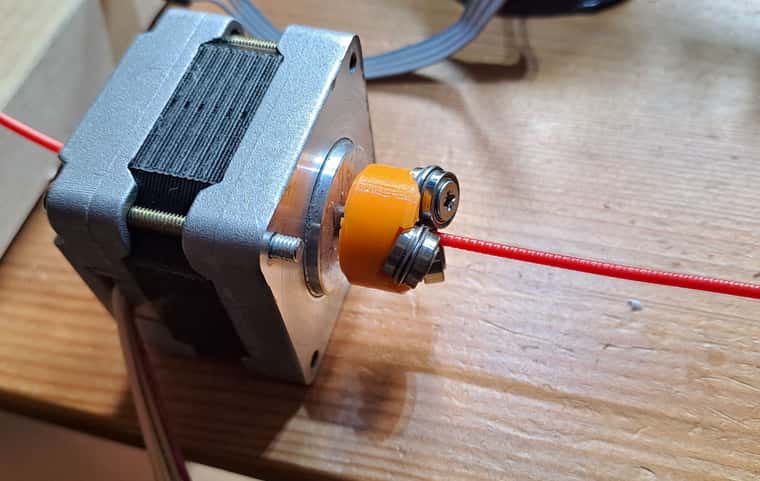
- It is possible to use a mix of different size bearings. My best extruder has two MF95ZZ bearings which have a 10mm flange. To avoid interference I use a smaller third bearing and mount the three of them slightly non-symmetrically around the filament axis. The slightly larger bearings have more grip.
- Depending on which country you're in, metric or imperial may be easier to source.
I, like @rqthree, have found a 0.1mm bite to be about perfect. More than that and it increases drag. Less than that and it both reduces thrust and also makes the tolerances much tighter, e.g. something like a 0.02mm error is a much bigger proportion of a 0.05mm bite than of 0.1mm.
There is nothing particularly special about 9.1mm. It's what I was targeting when I made my videos because it was about 0.1mm smaller than the diameter of the unground flange and I wanted to take off as little material as possible. Realistically, I could have gone for 9.15mm. My primary considerations for diameter are:
- Less grinding takes less time and effort and leaves fewer chances for machining errors.
- You can always take more off if necessary but you can't put it back on, so aim for larger and adjust to smaller if need be. e.g. if you want the same diameter for all the bearings and one accidentally ends up a bit smaller you can then make the others smaller too.
- I have found that larger diameters grip the filament better. I am guessing this is because the bite has a different shape with a bit more overlap.
- As @rqthree says, if you are printing your carrier then it's easier to make a custom carrier for whatever sizes you ended up grinding the bearings.
Drag on the filament is minimal as long as the bite is small enough. @rqthree initially designed a counter-torque mechanism into his extruder but later found it was not needed. The back-torque provided by the melted filament in the nozzle is sufficient. I benefited from this knowledge and have never even implemented a counter-torque. You do see a bit of backlash and it varies a bit by filament type. You may find retraction distances benefit from a bit of re-tuning. But I have not found it affects the print. Obviously consistent filament diameter becomes an important factor, but any decent filament these days has fine tolerances. It also helps if you minimise the path length through the hotend heatsink as this decreases the springiness of the filament section between the extruder and the nozzle.
Speed: there are a couple of guys on the CroXY Discord server who are exploring using VDE for high-speed. The simplicity and weight considerations are just too tempting. At high enough speeds VDE does under-extrude. There can also be issues with having to run the motor hotter which is problematic with the filament running through the shaft. More flanged bearings definitely help under-extrusion but they add drag and increase the likelihood of multiple grooves making a mess of each other. A mix of larger and smaller bearings mounted asymmetrically is also helpful. Firmware can help a bit as well, Marlin now has nonlinear extrusion and I think someone (@oliof maybe) said that RRF has has this feature for ages. Possibly Klipper does as well, I don't know. The guys at CroXY are, I think, experimenting with drilling a larger hole in the motor shaft and lining it with PTFE tubing. Mounting the motor on the hotend heatsink and sharing cooling air with the heatsink is also something to explore.
One idea I may go back to one day is a two bearing VDE. This required the filament path to be constrained by the walls of the hole leading up to the bearings, so adds friction, but it would allow for much larger bearings without any risk of interference.
@rqthree's observations about using PLA for a printed carrier match my experience. I have not experimented widely here but in my best round of testing I did swap from PETG to PLA when I noticed there was a difference.


