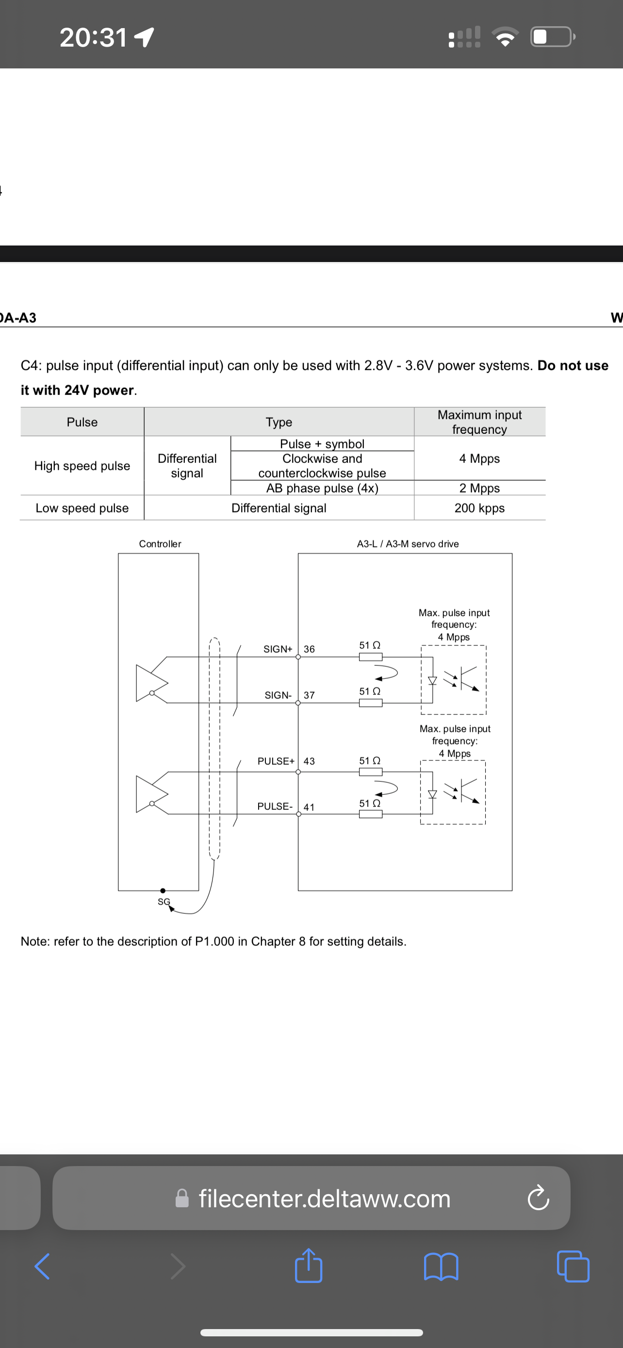
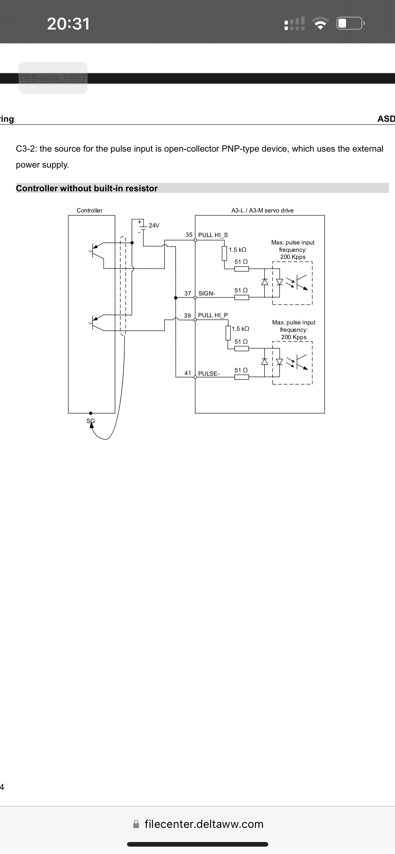
6XD - AC Servo drive (single-ended and differential signal)
-
@T3P3Tony Hi!
Quick question, If I would connect one more 6XD on the CAN-FD line as a "slave", I would love to connect it like this:
6XD -> 6XD(Slave) ----------- Longer CAN cable to the head of the machine ------------>3HC -> 3HC(Termination)
But as mentioned in Duet Documentation, 6XD has only one CAN-FD connection and it should be connected last in line if used as Slave, in that case, I would need to run a new cable from the head of the machine back to the enclosure where the rest of the electronic is and I don't like that, is there any other option?
Thank you,
-
@Zdenko it's acceptable to have short stub connections on the CAN bus. You should cut the CAN termination jumper trace on the 6XD that is not at the end of the bus.
Is there a reason why you want to use external drivers for all these motors?
-
@dc42 Hi,
I am looking for a way to connect 7 more steppers, as I can not use the 6XD which has timings set for two axis (X and Y) for external AC Servo Drivers, and as these timings are too fast external stepper motor drivers I need to find another solution that is cost-effective.
Now I basically have 4 STEP/DIR outputs on 6DX that can not be used because of this setup, so I need a way to have at least an additional 4 STEP/DIR outputs that are not "triggered" by those timings for X and Y Servo axis.
I would need 4 STEP/DIR outputs, or some combination of Duet 3 hardware to reach 7 integrated motor drivers, in that case, I would not need 7 external drivers.
If I go in the direction of Duet hardware, I would need two additional 3HC and one 1HC to have 7 integrated motor drivers, and that is in the end more expensive than one additional 6XD and 7 external drivers (where I need to buy 5 more only as I already have two)
With an additional 6XD, I would probably be more flexible, and I would only use 4 STEP/DIR from the board.
3 - Step/Dir outputs for (Two Stepper Drivers in parallel) = 6 drivers
1 - Step/Dir output for Conveyor Width Driver = 1 driverIf there is any other solution, I would be happy to hear.

-
@Zdenko what size stepper motors are they? A Duet 3 Mini and Duet 3 Mini 2+ used as an expansion board to the 6XD might be an option.
-
@dc42 Hi!
6pcs - Nema 17 26Ncm(36.82oz.in) 1.2A 42x42x30mm
1pc - Dual Shaft Nema 17 Nominal Voltage: 4.83V 1.5A 42x42x60mm -
@Zdenko yes Duet 3 Mini with the Mini2+ expansion can easily drive those.
-
@dc42 Hi,
Thank you, that makes sense, it would be the best solution, all would be integrated into the Duet3 Eco system, no external drivers would be required, space in an enclosure will be saved, and no additional wiring would be needed.
When it comes to connecting Duet 3 Mini 5+ with the rest of the Duet3 hardware in my case with 6XD and 2 pieces of 3HCs, to connect it on the CAN-FD line I would only need a short "stub" for CAN-FD and configure the Duet 3 Mini 5 config.g with M954 and set the CAN-FD ID, all other is then configured in 6XD config.g right?
As I have motors that are working in parallel, in config.g, drivers should have the same "letter of axis" assigned to Drivers that are moving at the same time, is that correct?
-
@Zdenko yes that's correct. Declare the axis motors using the M584 command.
The CAN bus needs to be terminated at both ends and there should be no terminators on other boards. If both the 6XD and the Duet 3 Mini will be physically at one end of the bus then I suggest you disable the termination resistor on the 6XD. So electrically the Duet 3 Mini will be at the end of the bus and the 6XD will be on a stub.
-
@dc42 Hi!
Ok, will place an order for the additional Duet HW, hopefully I will manage all connections without any issues.

Thank you,
-
@Zdenko Can you upload a picture of how you installed the resistors ?
-
@Zseven Hi,
It is a bit messy as all of it is outside of the encolure now, there are two resistors, one for STEP and one for DIR, I soldered them on the wire terminals and insert them in a connector, you will need to put some shrinking tube so that you don't short the pins/wires.
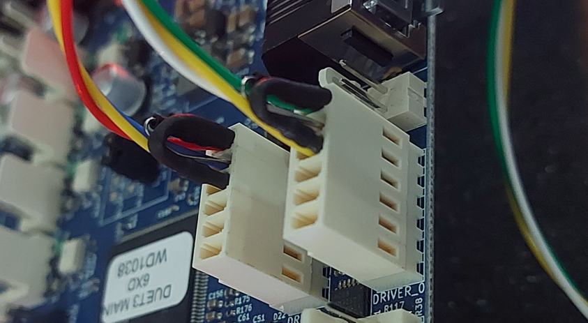
@dc42 Hi,
I received Duet 3 Mini5+ and Duet 3 Mini 2+, I managed to get it working without any issues for now, first I was super scared as the conveyor width stepper was making super weird noise then I researched a bit and found out that I needed this:
M569 P05.0 D3 H50 v50 S0; Conveyor_Width
M915 P05.0 T50After adjustment, the motor is working well, no more weird noises, now I need to finish 3 "Zones" of the conveyor, and sensors and put all the electronics in the Industrial enclosure, this should all be easy.

https://www.youtube.com/watch?v=PELvjKmPtk0&feature=youtu.be
This combination of Duet 3 Mini5+,Duet 3 Mini 2+,6XD and 2x3HCs, was a super nice decision, thank you.
Zdenko,
-
@Zdenko Thank you very much !
-
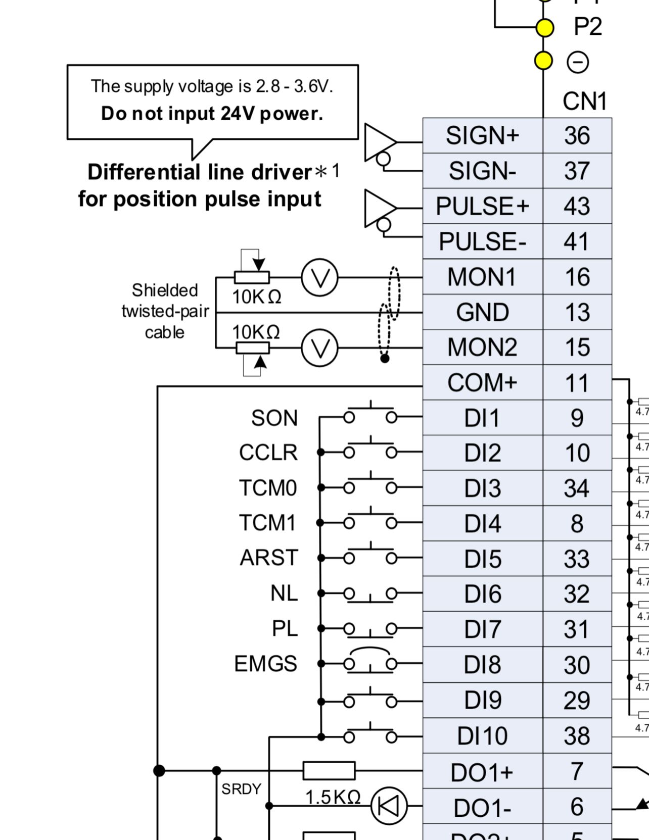
Hello ,
I have this servo controller, can I connect it directly to the 6Xd ? Because that stands for Puls and Signal max 3.6V. -
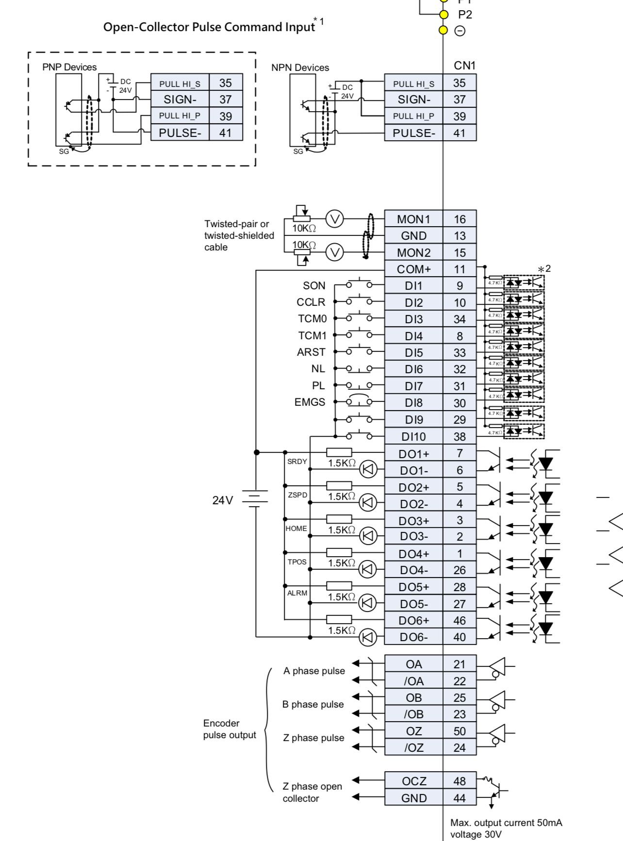
Or is it better to go via open-collector ?
-
@Zseven sadly there is no standard interface for external drivers or servo drives. There are at least 4 different ones:
- Opto isolated inputs requiring 5V input at 5 to 10mA, intended to be driven by open collector/open drain outputs.
- Standard 3V differential inputs as used by RS422/RS485 systems.
- Differential inputs but requiring more than 3V drive (e.g. Clearpath servos need 5V).
- As #1 but requiting 24V drive, intended to be driven by PLCs.
The most common is #1 so Duet 6XD supports it directly. Duet 1XD supports #1 and #3, and will generally work with #2 as well because the inputs don't normally mind being overdriven a little (if they do then series resistors can be added).
From the information you posted, it appears to me that your drivers support #2 and #4. The 6XD doesn't support either directly, because the open drain outputs are rated to 5V not 24V.
We made provision on the 6XD to add a daughter board to generate different signal levels, but we haven't produced any such daughter boards yet.
-
@dc42 What other information do you need?
Can't I just convert the 5v to 3v with a 10ohm resistor?
I have a 6xd board ..that is supposed to drive xyz with servo motors .
I have chosen these faithfully as they have a save torque off function. So that the drives can offer when the door is open.
Render from the printer that ist in work
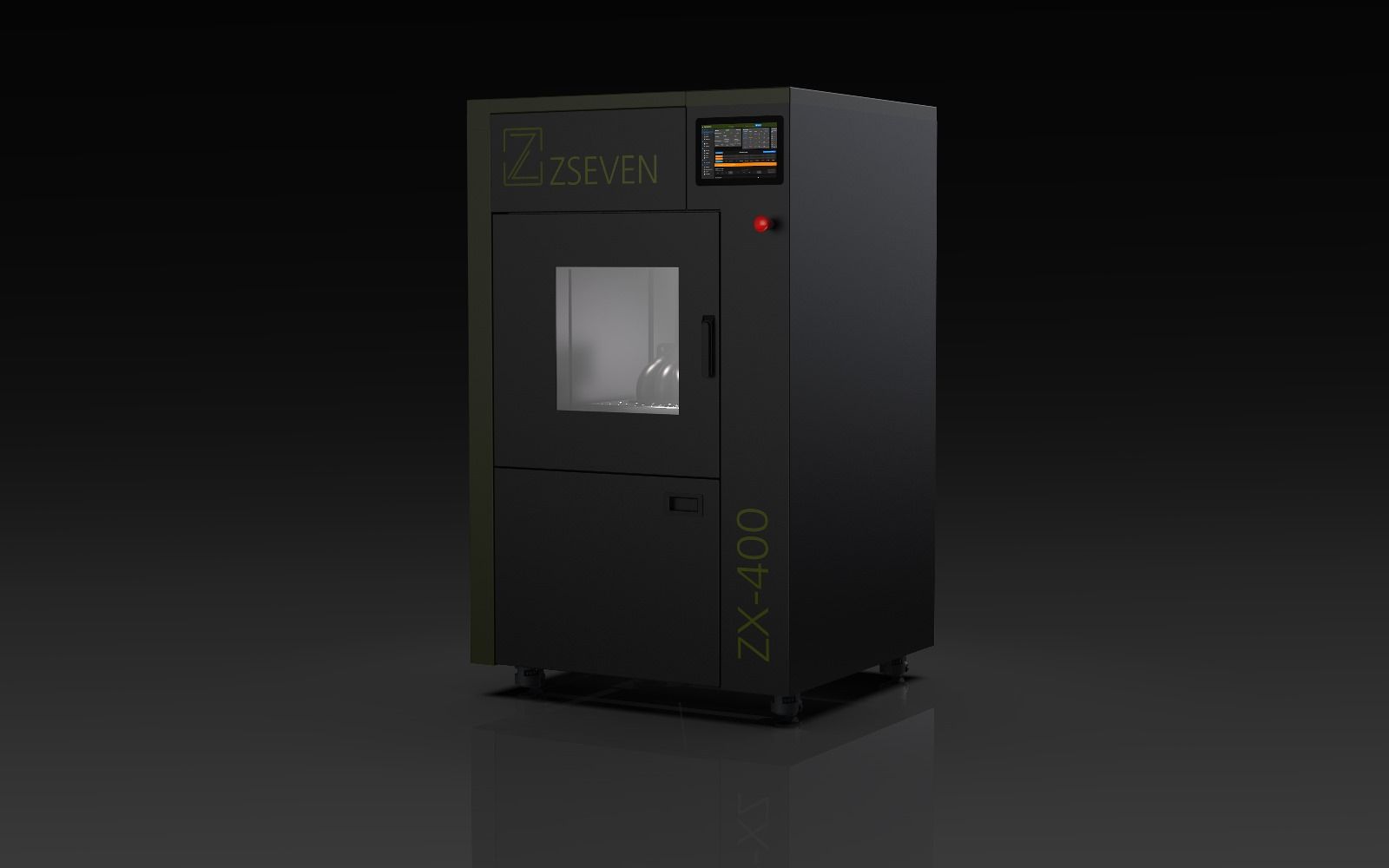
-
Here is the plan from the documentation
-
I have spoken to the manufacturer on the phone.
The documentation is wrong. They say it has to be at least 2.8-3.6 volts and a maximum of 5 volts. -
hi,
I am trying to use the same AC servo drive and motor, but i am a bit lost with the motion controller settings.
Could you let me know what's your's.
I am trying to connect this using a 1xd formelly used to run an external nema driver but i am here lost with AC servo motors.
For now it is wired in single ended mode, would you recommend differential mode ?thanks for the help !
