Connecting Silicon Heaters
-
@jens55 Thanks for your answer I connected one of the heaters for testing but it keeps heating, I cannot get the problem? why is it keep heating?
-
@ertence See this post for an example: https://forum.duet3d.com/topic/6534/connecting-a-ssr-between-duet-and-heated-bed/7
-
@stephen6309 Hello again. I check the post you mentioned. but I'm a newbie to be honest haven't noticed any problem. SSR immediately opens when I plug in the power. I can see the temperature but cannot control the relay as i said earlier
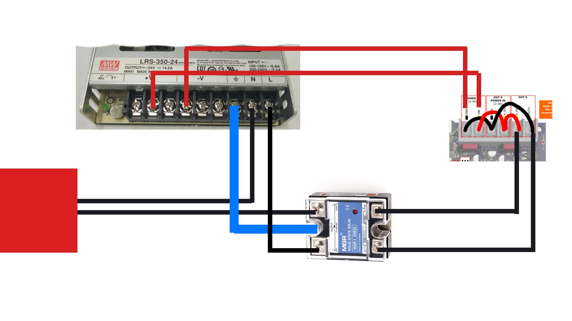
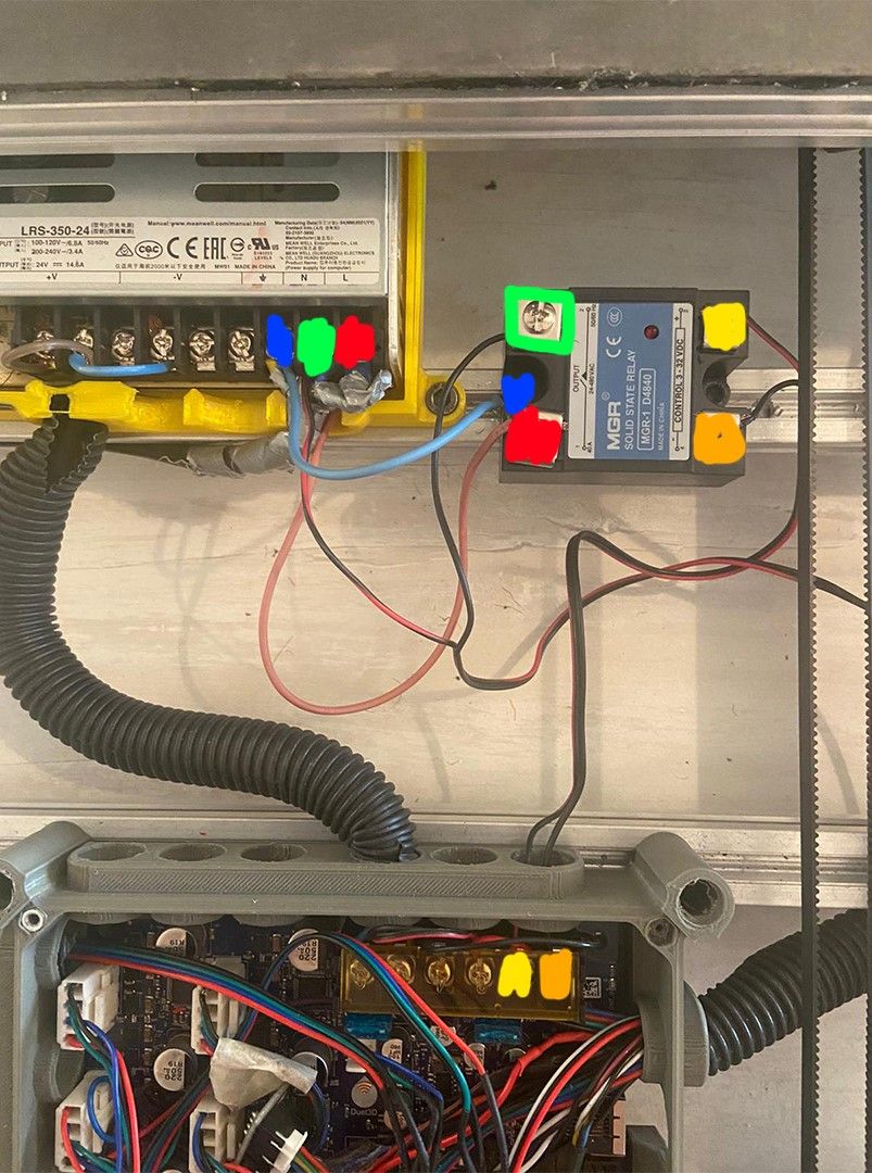
Here is my config and bed wiring
; Configuration file for Duet 3 (firmware version 3) ; executed by the firmware on start-up ; ; generated by RepRapFirmware Configuration Tool v3.2.2 on Tue Jan 26 2021 16:38:54 GMT+0100 (Central European Standard Time) ; General preferences G90 ; send absolute coordinates... M83 ; ...but relative extruder moves M550 P"nøkk3d" ; set printer name M564 H0 ; Network ;M551 P"ERTENCE" ; set password M552 P192.168.1.21 S1 ; enable network and set IP address M553 P255.255.255.0 ; set netmask M554 P192.168.0.1 ; set gateway M586 P0 S1 ; enable HTTP M586 P1 S0 ; disable FTP M586 P2 S0 ; disable Telnet ; Drives M569 P0 S1 ; physical drive 0.0 goes forwards M569 P1 S1 ; physical drive 0.1 goes forwards M569 P2 S1 ; physical drive 0.2 goes forwards M569 P3 S0 ; physical drive 0.3 goes forwards M569 P4 S0 ; physical drive 0.3 goes forwards M569 P5 S0 ; physical drive 0.3 goes forwards M584 X5 Y1:2 Z3 E4 ; set drive mapping M350 X16 Y16 Z16 E16 I1 ; configure microstepping with interpolation M92 X80.00 Y80.00 Z400.00 E436.54 ; set steps per mm M566 X900.00 Y900.00 Z60.00 E500.00 ; set maximum instantaneous speed changes (mm/min) M203 X15000.00 Y15000.00 Z400.00 E500.00 ; set maximum speeds (mm/min) M201 X500.00 Y500.00 Z25.00 E400.00 ; set accelerations (mm/s^2) M906 X1400 Y2500 Z2500 E1700 I30 ; set motor currents (mA) and motor idle factor in per cent M84 S30 ; Set idle timeout ; Axis Limits M208 S1 X0 Y-35 Z-5 ; set axis minima M208 X10000 Y490 Z500 S0 ; set axis maxima ; Endstops M574 X1 S1 P"io4.in" ; configure active-high endstop for low end on X via pin io0.in M574 Y1 S1 P"io0.in" ; configure active-high endstop for low end on Y via pin io1.in M574 Z1 S1 P"io3.in" ; configure active-high endstop for low end on Z via pin io2.in ; Z-Probe M950 S0 C"io7.out" ; create servo pin 0 for BLTouch M558 P9 C"^io7.in" H5 F120 T6000 ; set Z probe type to bltouch and the dive height + speeds G31 P500 X-30 Y-2 Z3.5 ; set Z probe trigger value, offset and trigger height M557 X20:980 Y10:490 S120 ; define mesh grid ; Heaters M308 S0 P"temp2" Y"thermistor" T100000 B4138 ; configure sensor 0 as thermistor on pin temp0 M950 H0 C"out2" T0 Q1 ; create heater output on out0 and map it to sensor 0 ; disable bang-bang mode for heater and set PWM limit M143 H0 S70 ; set temperature limit for heater 0 to 70C M140 P1 H0 M308 S1 P"temp1" Y"thermistor" T100000 B4138 ; configure sensor 1 as thermistor on pin temp1 M950 H1 C"out1" T1 Q1 ; create heater output on out1 and map it to sensor 1 ; disable bang-bang mode for the bed heater and set PWM limit M143 H1 S70 ; set temperature limit for heater 1 to 70C M140 P2 H1 M308 S2 P"temp3" Y"thermistor" T100000 B4138 ; configure sensor 1 as thermistor on pin temp1 M950 H2 C"out3" T2 Q500 ; create heater output on out1 and map it to sensor 1 ; disable bang-bang mode for the bed heater and set PWM limit M143 H2 S350 ; set temperature limit for heater 1 to 70C M307 H0 A200.8 C850.6 D2.0 S1.00 V24.0 B0 M307 H1 A200.0 C850.0 D2.0 S1.00 V24.0 B0 M307 H2 A491.0 C185.5.0 D4.9 S1.00 V24.0 B0 ; Fans M950 F0 C"out8" Q3000 ; create fan 0 on pin out4 and set its frequency M106 P0 S0 H-1 ; set fan 0 value. Thermostatic control is turned off M950 F1 C"out7" Q3000 ; create fan 1 on pin out5 and set its frequency ; set fan 1 value. Thermostatic control is turned on M106 P1 T45 S1.0 H2 ; Tools M563 P0 D0 H2 F0 ; define tool 0 G10 P0 X0 Y0 Z0 ; set tool 0 axis offsets G10 P0 R0 S0 ; set initial tool 0 active and standby temperatures to 0C ; Custom settings are not defined M501 -
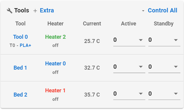
@ertence also it says beds are off but it's
 heating uncontrollably
 -
@ertence You don't want to be putting power IN to the OUT0 connector with the SSR.
IE, in your picture the last two daisy chains
-
@rushmere3d

Here is a more clear version. how we fix that problem -
@ertence On the duet3 6hc. Where the OUT0 in connected to the SSR, that is the only thing you want in those two screw terminals. DO NOT put 24v into there, that is powering the SSR from start-up.
-
@ertence I'll be honest I don't like your wiring. Please buy some suitable wire and connectors.
-
@ertence Also your config.g doesn't seem correct, your bed needs to have Out0 as it's pin.
How many beds do you?
-
This should be the config for a bed on OUT0, notice the thermistor locations and both are being controlled from OUT0 (How you have the SSR connected)
; Heaters M308 S0 P"temp0" Y"thermistor" T100000 B4138 ; configure sensor 0 as thermistor on pin temp0 M950 H0 C"out0" T0 Q10 ; create heater output on out0 and map it to sensor 0 ; disable bang-bang mode for heater and set PWM limit M143 H0 S70 ; set temperature limit for heater 0 to 70C M140 H0 M308 S1 P"temp1" Y"thermistor" T100000 B4138 ; configure sensor 1 as thermistor on pin temp1 M950 H1 C"out0" T1 Q10 ; create heater output on out1 and map it to sensor 1 ; disable bang-bang mode for the bed heater and set PWM limit M143 H1 S70 ; set temperature limit for heater 1 to 70C M140 H1 -
@rushmere3d said in Connecting Silicon Heaters:
@ertence On the duet3 6hc. Where the OUT0 in connected to the SSR, that is the only thing you want in those two screw terminals. DO NOT put 24v into there, that is powering the SSR from start-up.
How is the SSR going to be controlled if there is no signal being fed to the control inputs.
Without some source of positive voltage to the OUT 0 POWER IN V_OUT0 terminal there will be nothing appearing on the OUT 0 V_OUT0 terminal.
Frederick
-
@fcwilt look at his picture and I didn't say not to power the OUT0 input.
-
@rushmere3d said in Connecting Silicon Heaters:
@fcwilt look at his picture and I didn't say not to power the OUT0 input.
I cannot make out what is actually there. Based on the "color blobs" the SSR was being fed from OUT 0.
Frederick
-
@fcwilt What about other picture where they have daisy chained the power in all the screw terminals.
-
@rushmere3d said in Connecting Silicon Heaters:
@fcwilt What about other picture where they have daisy chained the power in all the screw terminals.
Well let's hope they didn't actually do that. It reflects a very poor understanding of what each set of terminals do.
Frederick
-
@fcwilt said in Connecting Silicon Heaters:
Well let's hope they didn't actually do that.
Well it would explain why the heater is always on by default.
-
Hello again thanks for the answers while I was waiting for the answers I realized the problem was from the config then I see the replies I disconnected the 24v from out0. also changed the bed output from out0 to out2. everything is working well right now sorry for the messy wiring and bad "color blob" wiring diagram. it was my first project
Thanks to everyone.