Problem with Mesh Bed Compensation
-
Hello, everyone,
I have a problem with Mesh Bed Compensation and I can't find a solution.Let's start with a description of the printer:
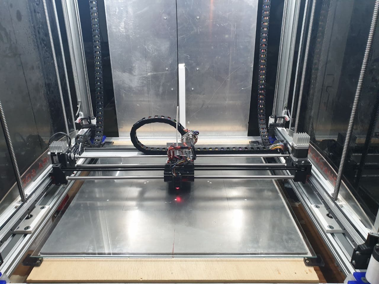
It's a Cartesian with a fixed print bed and 4 ball screws, with as many motors, regarding the Z axis.Board: Duet 2 WiFi (2WiFi)
Firmware: RepRapFirmware for Duet 2 WiFi/Ethernet 3.3 (2021-06-15)
Duet WiFi Server Version: 1.26; Communication and general M111 S0 ; Debug off M550 P"Quadra 600" ; Machine name and Netbios name (can be anything you like) ;*** Networking M552 S1 ; Turn network on M586 P0 S1 ; enable HTTP M586 P1 S0 ; disable FTP M586 P2 S0 ; disable Telnet M555 P2 ; Set output to look like Marlin G21 ; Work in millimetres G90 ; Send absolute coordinates... M83 ; ...but relative extruder moves ; Drives M569 P0 S0 ; X Axis - physical drive 0 goes forwards M569 P1 S0 ; Y Axis - physical drive 1 goes forwards M569 P3 S1 ; Extrusor - physical drive 3 goes forwards M569 P5 S0 ; Z1 Axis - physical drive 5 goes forwards M569 P6 S0 ; Z2 Axis - physical drive 6 goes forwards M569 P7 S0 ; Z3 Axis - physical drive 7 goes forwards M569 P8 S0 ; Z4 Axis - physical drive 8 goes forwards M584 X0 Y1 Z5:6:7:8 E3 ; set drive mapping ;M350 X16 Y16 Z16 E16 I1 ; configure microstepping with interpolation M92 X80.226 Y80.0961 Z800.00 E401.5 ; set steps per mm M350 X128 Y128 Z128 E128 I1 ;Default M203 X6000 Y6000 Z300 E1200 I30 ; set maximum speeds (mm/min) M203 X12500 Y12500 Z900 E3600 ;Default M201 X500 Y500 Z20 E250 ; set accelerations (mm/s^2) ;#4 M201 X1250 Y1250 Z50 E2750 M201 X500 Y500 Z50 E2750 ; #5 ;Default M566 X900 Y900 Z12 E120 P0 ; set maximum instantaneous speed changes (mm/min) ;M566 X1800.00 Y1800.00 Z24.00 E1200.00 P1 M566 X450.00 Y450.00 Z24.00 E1200.00 P1 ;Default M204 P10000 T10000 ; Set printing and travel accelerations (mm/s^2) M204 P5000 T5000 ; corrente motori 60-90% della corrente nominale ; AsseX = 1500-2250 (max 2500mA) ; AsseY = 1500-2250 (max 2500mA) ; AsseZ = 1500-2250 (max 2500mA) M906 X2250 Y2250 Z1875 E940 I30 ; set motor currents (mA) and motor idle factor in per cent (60-90% of nominal current) M84 S30 ; Set idle timeout ; Axis Limits ;M208 X0 Y0 Z-0.20 S1 ; set axis minima ;M208 X602 Y604 Z606 S0 ; set axis maxima M208 X0:602 Y0:604 Z-3:606 ; Endstops M574 X1 S1 P"xstop" ; configure active-high endstop for low end on X via pin xstop M574 Y1 S1 P"ystop" ; configure active-high endstop for low end on Y via pin ystop M574 Z1 S1 P"duex.e2stop+duex.e3stop+duex.e4stop+duex.e5stop" ; configure active-high endstop for low end on Z via pin duex.e2stop+duex.e3stop+duex.e4stop+duex.e5stop ;M574 Z1 S1 P"duex.e5stop" ; Emergency Stop M950 J1 C"!duex.e6stop" M581 P1 T0 C0 S0 ; Filament runout sensor M591 D0 P2 C"e0stop" S1 ; filament monitor connected to E0 endstop M669 K0 ; select Kinematics Y to react with X and Z ; ZProbe -- BL-Touch M558 P9 C"^zprobe.in" H5 F90 T7500 ;A10 S0.03 ; set Z probe type to bltouch and the dive height + speeds probe up to 5 times until 2 consecutive readings are within 0.005, if none average of 5M307 H3 A-1 C-1 D-1 M950 S0 C"duex.pwm5" ; create servo pin 0 for BLTouch G31 P25 X0 Y-70 Z2.80 ; set Z probe trigger value, offset and trigger heigh ; Mesh Bed Compensation M557 X0:602 Y0:604 P15 ; define mesh grid ; Bed Heaters M308 S0 P"bedtemp" Y"thermistor" T100000 B4092 ; configure sensor 0 as thermistor on pin bedtemp M950 H0 C"bedheat" T0 ; create bed heater output on bedheat and map it to sensor 0 M307 H0 R0.420 C563.0 D4.59 S1.00 B0 ; enable bang-bang mode for the bed heater and set PWM limit M140 H0 ; map heated bed to heater 0 M143 H0 S120 ; set temperature limit for heater 0 to 120C ;M140 H-1 ; disable heated bed (overrides default heater mapping) ; Extruder Heaters M308 S1 P"e0temp" Y"thermistor" T100000 B4092 ; configure sensor 1 as thermistor on pin e0temp M950 H1 C"e0heat" T1 ; create nozzle heater output on e0heat and map it to sensor 1 M307 H1 R2.677 C134.2:124.8 D6.30 S1.00 V24.3 ; disable bang-bang mode for heater and set PWM limit M143 H1 S280 ; set temperature limit for heater 1 to 280C ;Layer Fan M950 F0 Q250 C"fan0" ; create fan 0 on pin fan0 and set its frequency ;M106 P0 S0 H-1 C"Layer Fan" ; set fan 0 value. Thermostatic control is turned off ;Extruder Fan M950 F1 Q250 C"fan1" ; create fan 1 on pin fan1 and set its frequency M106 P1 S1 H1 T45 C"Extruder Fan" ; set fan 1 value. Thermostatic control is turned on ; Tools M563 P0 D0 H1 F0 S"Estrusore MK8" ; define tool 0 G10 P0 X0 Y0 Z0 ; set tool 0 axis offsets G10 P0 R0 S0 ; set initial tool 0 active and standby temperatures to 0C ; Miscellaneous M575 P1 S1 B57600 ; enable support for PanelDue ;Accelerometer M955 P0 C"spi.cs4+spi.cs3" I20 M18 Z E0 T0The current problem with my printer is that the X axis tends to deform slightly when the head passes over it. The two Ø12 mm round bars are obviously not strong enough to support the weight of the head with the Hemera "direct" extruder.
The Z-axis is reset using optical sensors.
Then the XY bridge is levelled with the file bed.g (copied on this forum from a post by fcwilt).; --- prepare to level bed --- ; M671: Define positions pf manual bed levelling screws or Z leadscrews ; Xnn:nn:nn... list of between 2 and 4 X coordinates of the leadscrews that drive the Z axis or the bed levelling screws ; Ynn:nn:nn... list of between 2 and 4 Y coordinates of the leadscrews that drive the Z axis or the bed levelling screws ; Snn maximum correction allowed for each leadscrew in mm (optional, default 1.0) ; Pnnn pitch of the bed levelling screws (not used when bed levelling using independently-driven leadscrews). Defaults to 0.5mm which is correct for M3 bed levelling screws ; Fnn fudge factor, default 1.0 M671 X-110:-110:720:720 Y130:470:470:130 S50 ; position of lead screws M291 R"Leveling bed" P"Please wait..." T0 ; --- level bed leveling --- while true ; run leveling pass ; --- probe near lead screws - YOU WILL NEED TO ADJUST THE X AND Y VALUES TO SUIT YOUR PRINTER --- G30 P0 X5 Y130 Z-99999 ; probe near lead screw #1 G30 P1 X5 Y470 Z-99999 ; probe near lead screw #2 G30 P2 X595 Y470 Z-99999 ; probe near lead screw #3 G30 P3 X595 Y130 Z-99999 S4 ; probe near lead screw #4 ; check results - exit loop if results are good if move.calibration.initial.deviation < 0.02 break ; check pass limit - abort if pass limit reached if iterations = 5 M291 P"Bed Leveling Aborted" R"Pass Limit Reached" abort "Bed Leveling Aborted - Pass Limit Reached" ; --- finish up --- ; --- set Z=0 datum which can be affected by leveling --- G1 X300 Y363 F6000 ; move to center of bed - ADJUST THESE FOR YOUR PRINTER G30 ; do single probe which sets Z to trigger height of Z probe M291 R"Leveling bed" P"Done" T0At this point, I start printing.
There are 2 commands in the gcode to be printed:
G32 ; BED Leveling
G29 S1 ; enables mesh compensationThe mesh (I don't have the mesh.g file) has been produced several times, both cold and hot, but it makes little difference.
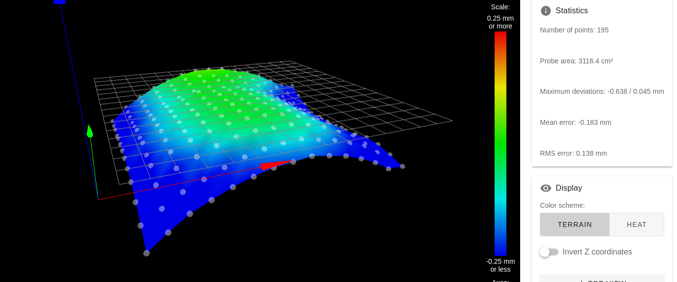
I'm trying to print 9 squares 20x20 mm (only the first layer) in order to see if the print is correct on the whole plane of the printer (600x600x600 useful). And here's the problem I can't solve.
In the diagram below, I identify with the letter P the "point" where the test square is printed.
P7 P8 P9
P4 P5 P6
P1 P2 P3The problems encountered are as follows:
P1 excessive height
P2 slightly reduced height
P3 the nozzle touches the plane
P4 acceptable height
P5 perfect height
P6 the nozzle touches the plane
P7 slightly excessive height
P8 the nozzle touches the plane
P9 low heightWhatever I try, the result does not change as I expect.
I have tried everything, including replacing the glass, but I see no improvement.I have the impression that the compensation is not happening as it should.
Can anyone give me some advice?
Thanks
Bernardo -
G31 P25 X0 Y-70 Z2.80With your probe offset so far in Y, the droop of the carriage is magnified. Because of the offset, the probe moves up and down with the rotation, while the nozzle, which is under the centre of rotation, moves forward and back. So the bed mesh is valid, but only if the nozzle is where the probe is!
If possible move the probe so it is to the side of the nozzle, with an X offset but no Y offset, rather than in front.
Ian
-
-
@droftarts said in Problem with Mesh Bed Compensation:
the probe moves up and down with the rotation
The rotation of what? I cannot picture what it is.
Frederick
-
-
Thanks.
I suspect those rods are indeed sagging under the load. The image of the height map you posted is exactly what you would expect to see with that kind of sag.
So you can live with what you have and let mesh compensation deal with it as best it can OR you can redesign your XY gantry to use something more rigid.
Frederick
-
@fcwilt At the moment I cannot change anything, so I would like to use compensation. The problem is that the compensation doesn't seem to work... because on the left side it manages to give me a relatively acceptable height in relation to the plane, while on the right side it doesn't. And I don't understand why.
Tomorrow I will try to modify the map manually, so that I can "force" the compensation only on the right side of the plate.The new deck is being designed, but it requires structural modifications that I cannot install on this one due to lack of space. I will also have to completely redo the Y-axis, which in this way has limitations that I don't like. But we'll talk about that in late spring!
-
Some folks have reported that mesh compensation is not working when it needs to move the probe below Z = 0 if the Z min limit of the bed is 0.
Is that perhaps what you are encountering?
Frederick
-
@fcwilt I had read this and in fact I set
M208 X0:602 Y0:604 Z-3:606
From what I understand, it is as if the compensation has a "limit" beyond which it cannot go.
In the P1 corner, for example, the compensation can correct the Z by more than 0.5 mm. In P3 and P6 this is not the case. I don't understand why and that's what I'd like to know.I don't know if changing the F (Fudge factor) parameter in M671 would improve this... (I still don't understand how it works)...
-
@fcwilt said in Problem with Mesh Bed Compensation:
@droftarts said in Problem with Mesh Bed Compensation:
the probe moves up and down with the rotation
The rotation of what? I cannot picture what it is.
Frederick
I drew you a picture.
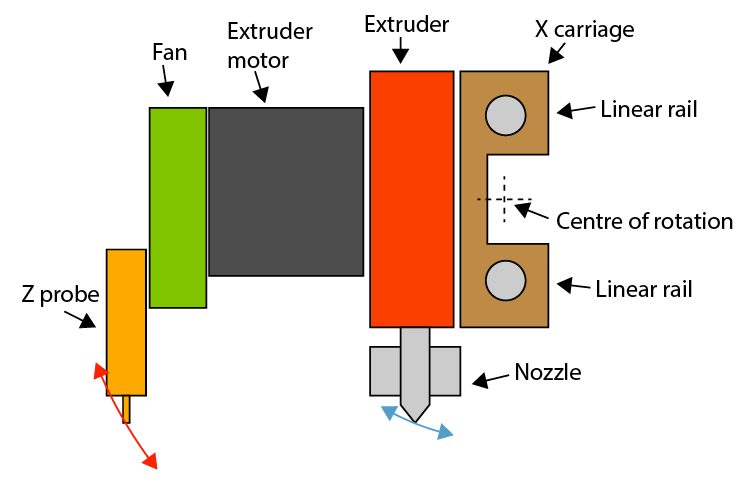
Any sag in the linear rail, and it is usually rotation of the carriage around the X axis, causes a Z probe offset in Y to rotate around the centre of rotation more vertically than the nozzle. The further the probe is offset, the worse the effect. In the above diagram, the Z probe is almost twice the distance from the centre of rotation than the nozzle, so it's an even worse problem, as the error is doubled.This may not be the issue @bernardomattiucci is encountering, as his linear rods are not stacked vertically, but if one linear rod is taking more weight that the other, or is bent, the same effect will be seen.
It's generally better to offset the probe in the X direction, because the probe will have the same rotation around the axis as the nozzle. However, the carriage must not rock, otherwise you get a 'sawtooth' type bed mesh (like the one seen in this thread).
Ian
-
@droftarts This is the head of my printer.
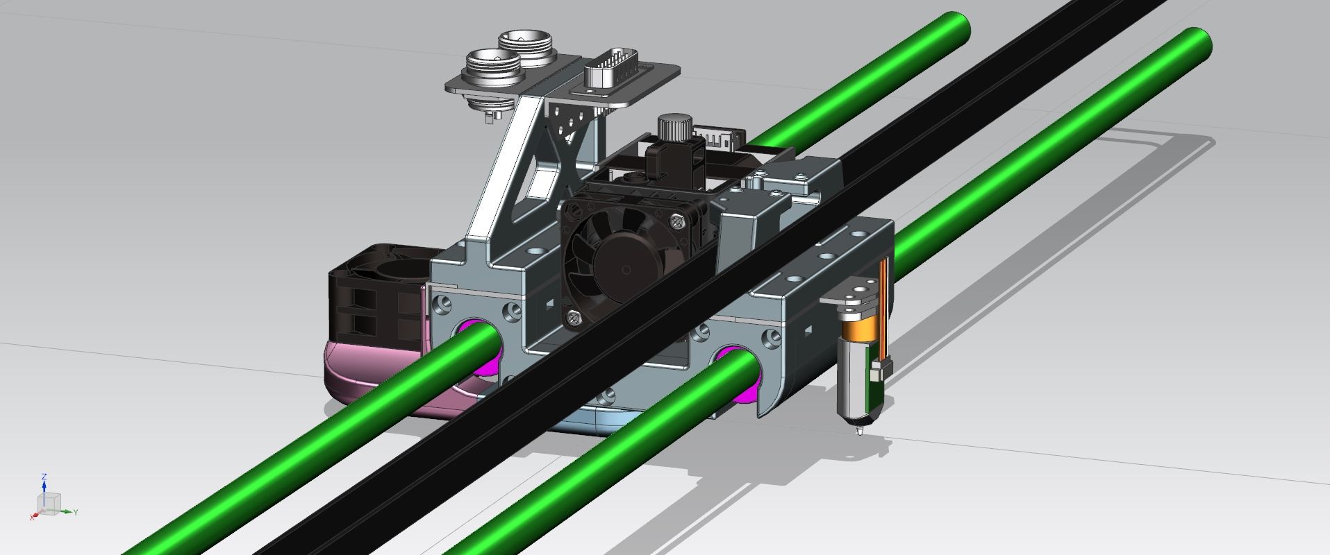
The stand with the connectors is different, as the one in the drawing I can't mount until I complete the printing of the components I need.
There is a little bit of wobble, and in fact I bought a LIS3DH accelerometer to try and find out which component is 'faulty'.
But apart from the oscillations, the problem is not mechanical, but electronic... that is, in the compensation of the mesh, which is carried out regularly and abundantly on the left side (looking at the previous photo) and much, much less on the right side.
-
@bernardomattiucci said in Problem with Mesh Bed Compensation:
that is, in the compensation of the mesh, which is carried out regularly and abundantly on the left side (looking at the previous photo) and much, much less on the right side.
I have not heard of that but it is easy enough to test for.
But that will have to wait until tomorrow.
Frederick
-
One way to narrow down whether the probe tilt is an issue is to set probe type to manual (m558 P0) which allows you do manually touch the nozzle to the bed by jogging to set each point. This can be time consuming for a detailed mesh, but the results would clearly show if the problem is with the probe results or something else.
-
problem solved!
I ran various tests, including making a 5x5 map with m558 p0. The results were not satisfactory and were complex to modify precisely.
So I made, first with BLTouch and then rewrote by hand, a custom 3x3 map, modifying only the values that I was interested in and in the way I wanted to for an acceptable print.The printer in question is a prototype... it is by no means the final version, but I need to print all over the plane and until now I had not had the need to use Mesh Bed Compensation.
Finally I've done it!
-
@bernardomattiucci said in Problem with Mesh Bed Compensation:
Glad to hear you got it working to your satisfaction.
a custom 3x3 map
I guess you know that a denser map is more common. On my printers it ranges from 15x15 to 20x20 points depending on the size of the printable area.
Good luck with your ongoing development.
Frederick
-
@fcwilt Yes, I know that, but at the moment I am not interested in exceptional quality. I just want it to print what I want, how I want it and without too many mistakes.
I will slowly replace the various "definitive" PLA parts with aluminium alloy equivalents, so that all the mechanics become more stable. At that point, having in the meantime replaced the round guides (X and Z with MGN15 recirculating ball bearings), I will be able to create the 20x20 mesh.Thank you
-
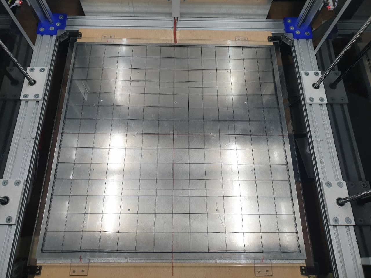
It's not perfect but it's still acceptable.
With a 5x5 or denser map, the result would undoubtedly be better, but having built the 3x3 map entirely by hand, with a series of print runs in succession, I can be satisfied. Also because, I repeat, it is a prototype!Test grid: 595x595x0.2 with 1% filling (printed in 32 minutes @25-30mm/s)
-
Good morning and Happy New Year to all,
with reference to this post, I wanted to point out that I have solved almost all the problems by completely redoing the print bed support. For some reason it was deforming due to heat, unevenly and this was creating levelling problems.
At the moment I am using an "aluminium tile", of those commonly used for suspended floors, and this has allowed me to solve the problem of mesh compensation.Now I'd just like to insert a "dynamic" control in the mesh.g file (I saw it in one of your files but I don't remember who or where) so as to use a 600x600 mesh when the object to be printed is large, and a 300x300 mesh when the object is smaller. maybe @fcwilt was the author... but I'm not sure.
Could you please help me?
