And with these 5 photos I close the discussion.
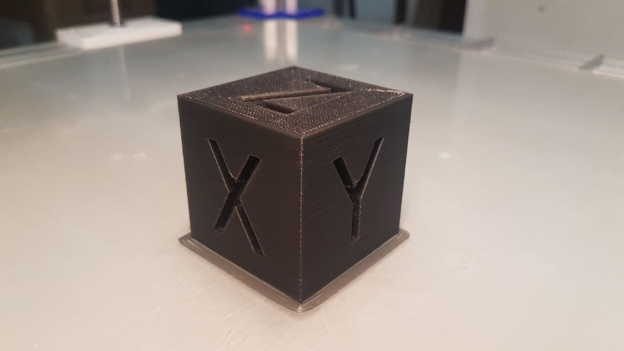
Thank you all
And with these 5 photos I close the discussion.
Thank you all
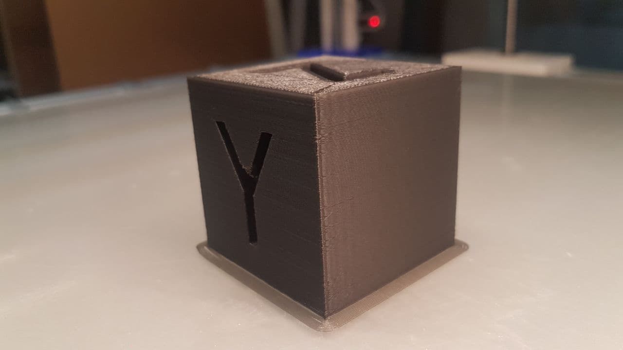
It's not perfect but it's still acceptable.
With a 5x5 or denser map, the result would undoubtedly be better, but having built the 3x3 map entirely by hand, with a series of print runs in succession, I can be satisfied. Also because, I repeat, it is a prototype!
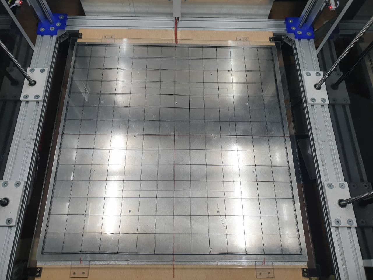
Test grid: 595x595x0.2 with 1% filling (printed in 32 minutes @25-30mm/s)
Everything starts moving ... and if it weren't for the power supply fan, you wouldn't hear anything (or almost)!
very beautifull!
Goodmorning everyone
I had entered the codes M566, M203 and M201 in the config.g file to find the speed "limits" of the X and Y axes.
Now the 3 instructions in the file have been commented out.
From the Console I get this:
Custom M566
;M566 X4000.00 Y4000.00 Z300.00 E1500.00           										; set maximum instantaneous speed changes (mm/min)

Original M566
Maximum jerk rates (mm/min): X: 900.0, Y: 900.0, Z: 12.0, E: 120.0, jerk policy: 0

Custom M203
;M203 X20000.00 Y20000.00 Z1000.00 E5000.00       										; set maximum speeds (mm/min)

M203
Max speeds (mm/min): X: 6000.0, Y: 6000.0, Z: 300.0, E: 1200.0, min. speed 30.00

Custom M201
;M201 X5000.00 Y5000.00 Z100.00 E4000.00           										; set accelerations (mm/s^2)

M201
Accelerations (mm/sec^2): X: 500.0, Y: 500.0, Z: 20.0, E: 250.0
I'll do some printing tests with the default values and let you know.
@fcwilt At the moment I cannot change anything, so I would like to use compensation. The problem is that the compensation doesn't seem to work... because on the left side it manages to give me a relatively acceptable height in relation to the plane, while on the right side it doesn't. And I don't understand why.
Tomorrow I will try to modify the map manually, so that I can "force" the compensation only on the right side of the plate.
The new deck is being designed, but it requires structural modifications that I cannot install on this one due to lack of space. I will also have to completely redo the Y-axis, which in this way has limitations that I don't like. But we'll talk about that in late spring!
Good morning
It all seems to work quite well.
Now I just have to figure out how to solve a problem on the Y axis, mostly due to the type of "transmission" used and complete the settings ... before moving on to the print tests!
This is the X axis test: https://youtu.be/UG27txKxALk
@fcwilt Yes, I know that, but at the moment I am not interested in exceptional quality. I just want it to print what I want, how I want it and without too many mistakes.
I will slowly replace the various "definitive" PLA parts with aluminium alloy equivalents, so that all the mechanics become more stable. At that point, having in the meantime replaced the round guides (X and Z with MGN15 recirculating ball bearings), I will be able to create the 20x20 mesh.
Thank you
I fixed the errors in the code.
if job.build != null
	if job.layer != null && job.layer <= 5
		M140 S50
	elif job.layer != null && job.layer > 5
		if job.layer < 20
			if heat.heaters[0].current < 40
				M140 S50
			if heat.heaters[0].current > 50
				M140 S40
		else
			M140 S0
if job.build != null
	if job.layer != null && job.layer <= 5
		M140 S50
	elif job.layer != null && job.layer > 5
		if ((job.file.numLayers*20)/100) < 20
			if heat.heaters[0].current < 40
				M140 S50
			if heat.heaters[0].current > 50
				M140 S40
		else
			M140 S0
seems to be working
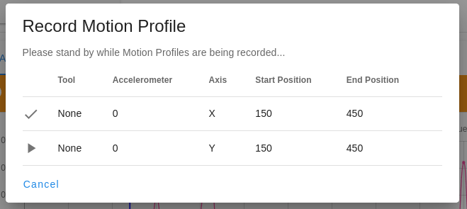
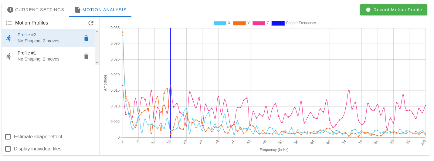
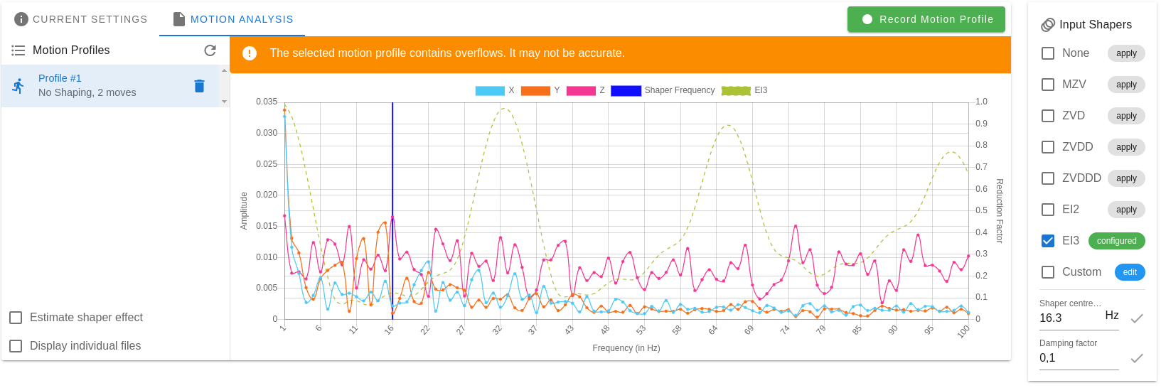
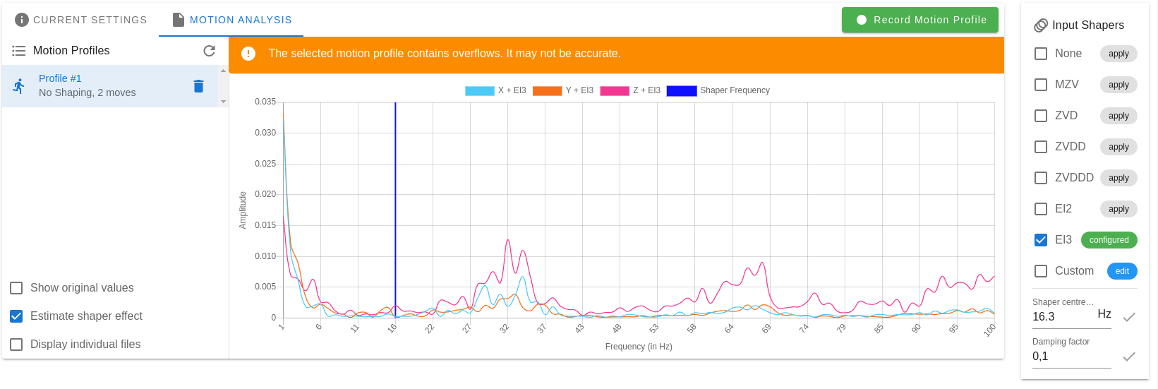
I have performed other tests and the result is still the same. Until a few firmware versions ago, I think before 3.2 but I don't remember well, when input shaping was an external plugin, the error "The selected motion profile contains overflows" never appeared. Then with an update it started to appear.
I rewired and not much has changed (i.e... now at least it works, albeit with data overflow).
Question: does the presence of this error, in any way affect the proper functioning of input shaping?
Thanks
Occasionally the plugin seems to get stuck. I don't know if it depends on something in my installation or if it is a bug in the plugin, because the data all seems to be there. Even the overflows!
I mounted the second section of usb3 cable and after a few unsuccessful attempts, it recorded the track without the error.
I'll do some more tests.
In the meantime, thank you
@droftarts I will test with the other half of the cable. But to solve the problem I have to figure out what it is and why that kind of "error" is generated. At the moment I have no idea what it is!
The first half of the cable I replaced with a USB-3.
Tomorrow I will prepare the other half and test it.... if it gives me any improvement in results I will install it, otherwise I will leave the current one.
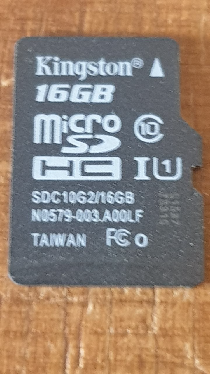
Wanting to buy a new SDCard, do you recommend BRAND and MODEL to get online?
I currently have this:
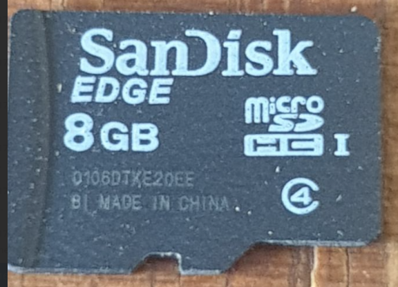
And before that there was this one:
@droftarts Using the "input shaping" plugin with the "record motion profile" button, the result is always the same: "The selected motion profile contains overflows. It may not be accurate."
Is there any way to solve the problem without necessarily replacing the SD-CARD?
One of the terminals on the Duet side connector, was not perfect and I had to redo it, changing the connector as well.
Now it works, so I would say this problem is solved.
Occasionally, during the "record motion profile" operation, it gives me some problems. I don't know if it depends, as I read, on the SD-Card or the cable that is not perfect. Patience!
@droftarts the problem is in the cable.
I just made one 30 cm long and it is seen regularly.
the problem is that my electronics are separate from the printer and the distance is considerable. It needs a well-shielded cable, which I don't have at the moment, so I had made one using a flat-cable, but evidently it is not shielded well. I will do more testing tomorrow and try to solve it!
Thanks
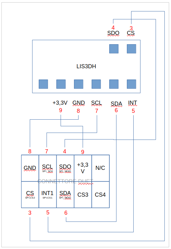
this is my current scheme, but the accelerometer is still not seen.
To premise that I have a Duex5 board connected, so I don't know if it can affect it.
Before the update, however, I was not getting any errors. This is 100% certain.
I had wires 3 and 4 (red colored numbers) connected to CS3 and CS4 and it was working.
@droftarts In fact, I'm double-checking because something doesn't feel right about the connections. I've been redoing them several times in the last few months and I may have made some mistakes.
