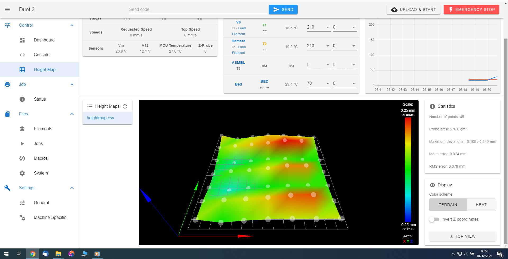
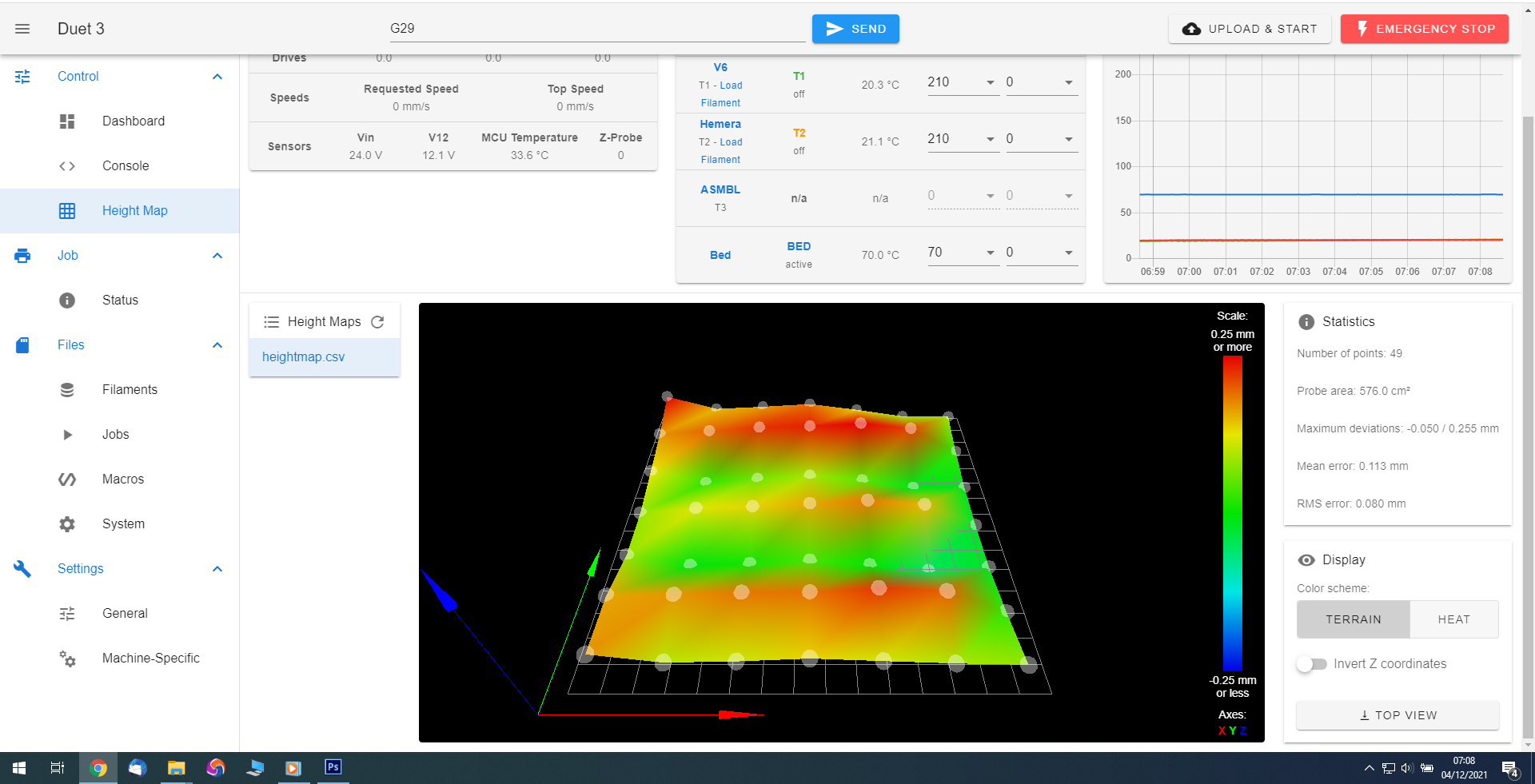
Very! strange height map results
-
I was looking at it sideways.
The wave effect is along Y, as you say.I will re-investigate.
-
I am puzzled; the machine is a CoreXY with the X rail supported on all-metal guides and roller bearings, with the Y axis carriages having lateral rails and wheels.
The rails seem perfect, when checking with a straight edge, and if one carriage had eg. a skewed roller, that should how up far stronger at the close end and much less near the good etc.
Plus the "wavelength" would not alter with the probe grid.
[I was expecting any mechanical problem to be in X, as that has a completely new carriage and the rail for that aligns the rollers vertically - but again I could not find any variation & everything is solid].
It's taken me a long time to get the setup something like right with this and I don't want to mess it up; it's running in SBC config with toolboards etc.
I'll try to find a spare SD and put the V3.3 setup on that.
-
@rjenkinsgb said in Very! strange height map results:
Y axis carriages having lateral rails and wheels
Maybe the wheel axles are out of center?
-
@rjenkinsgb said in Very! strange height map results:
Plus the "wavelength" would not alter with the probe grid.
if it was a deformation in the rails I agree, however a rocking type issue where the probe (and what its mounted on) rotated round a point could do this.
-
I've checked the track rollers on the X carriage, they are tight as both ends, and the probe mount seems to be rock solid.
I've just done a test by approaching the same point from 10mm plus or minus on X and getting the G30 result from both:
03/12/2021, 17:25:40	G30S-1
Stopped at height 3.050 mm
03/12/2021, 17:25:17	G1X150Y150F50
03/12/2021, 17:23:09	G01X160Y150Z10
03/12/2021, 17:22:45	G30S-1
Stopped at height 3.025 mm
03/12/2021, 17:22:18	G1X150Y150F50
03/12/2021, 17:21:43	G0X140Y150Z10
03/12/2021, 17:21:14	G32
03/12/2021, 17:21:14	Leadscrew adjustments made: -0.050 -0.455, points used 2, (mean, deviation) before (-0.204, 0.086) after (-0.000, 0.000)
03/12/2021, 17:20:53	Connected to 192.168.0.30
It's only .025mm different, which could partly be the probe warming up as I'd only just switched the machine on and let the bed get to temperature.
Repeating, it's still drifting slightly, but nowhere near the magnitude in the heightmap and consistently the same direction, so most likely a thermal effect.
03/12/2021, 17:30:54	G30S-1
Stopped at height 3.122 mm
.....
03/12/2021, 17:29:46	G30S-1
Stopped at height 3.112 mm
The next thing must be try it back with V3.3
-
@rjenkinsgb before trying back tracking to 3.3 can you try the single row "mesh" (across the "waves")
-
@t3p3tony said in Very! strange height map results:
before trying back tracking to 3.3 can you try the single row "mesh" (across the "waves")
It won't accept a single row:
M557 X0:240 Y150:150 S20Error: M557: bad grid definition: X range too small -
@rjenkinsgb ahhh, dammit. yes in that case 3.3 would be the next logical thing to do to eliminate or point to a firmware issue.
-
@t3p3tony
OK, having set up an SD card with V3.30 and put the same config in that:No change; it's not due to the beta firmware.
I'm trying to remember all the changes I made about the same time; there were several in a short time.
The original heightmap was from before I fitted the glass bed over the slightly curved aluminium one; I was trying to get it as flat as possible, as the heightmap showed an obvious dip between the front & back support bars.
Another change was adding G32 to level across the leadscrews, rather than using a single point G30 in the centre of the bed.
At the moment, I still have the wave effect.
However, trying the single point zero rather than dual point, it appears dual point makes things worse:
(I have adjusted the bed levelling screws slightly to try and get as near level as I can with an all zeros heightmap)This is now the result using G32. I have verified the leadscrew spacing etc.

But with a single G30 in the middle of the bed - still the waves, but without the right side being wrongly high:

I'll be trying to set up some measuring equipment later today to detect any head tilt; our gear for machine tool setup has magnetic bases and this machine is virtually all aluminium and plastic, I need to work out some suitable attachment points or brackets yet..
-
Tell tail pattern of backlash causing the probe to tilt.
-
Just done a test with a dial indicator under the head "cap":
https://www.youtube.com/watch?v=Gr6-FIdfnhA
There is no more than about +/- 10 microns spring when trying to squeeze or lift it relative to the rail, and jogging either way and back to the middle position of the three gives a similar range.
The gauge tip is on the underside of the printed cap and that is not dead flat, so the gauge reads differently either end - but returning to the centre position from either direction shows only a tiny error, which could be the gauge tip dragging on the rough surface.
I also tried the gauge at the other end, directly under one of the BLTouch mounting screws, and that gave a similar +/- ~10um movement spring when prying or squeezing against the rail. There is no flat surface at that end to try with X movement.
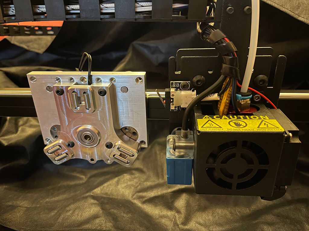
This is a photo of the new axis saddle plate against the original head, while I was working on the new toolhead; it uses steel track rollers with eccentric adjusters, identical parts to the original Tronxy linear track guides.
The large printed cap that anchors the belts and cables is held by two long M5 screws through the top corners and the whole thing is an extremely tight (interference) fit over the metalwork and through the screw positions, bracing it downwards.

So far, the only movements I can find are around an order of magnitude less that what is indicated in the height maps, and that's with force applied?
-
 undefined droftarts referenced this topic
-
It is very strange. Is there anything else that could be affecting the BLTouch? Have you watched it closely while probing?
-
@rjenkinsgb in your two Dec 4th images, the first had a bed temperature of 30 degrees, in the second 70 degrees, may thermal expansion be a cause? How is the bed fixed, by screws (so it can bend) and which type is the bed?
-
@phaedrux @rjenkinsgb
Same idea: I'd check the drag-chain if it causes the BLTouch mount bending/tilting. -
@o_lampe said in Very! strange height map results:
I'd check the drag-chain if it causes the BLTouch mount bending/tilting.
It uses the E3D spring trip arrangements to hold the cables as upright loops, so any "pull " is consistently towards the front centre.
Nothing was moving much or retaining any offset when I was deliberately trying to create head<>rail movements & the BLTouch is attached directly and rigidly to the underside of the printed cap I had the dial gauge on.
I'll do more measurements and gauge tests when I get chance.
I'll also try running heightmap with a tool on the head - the Hemera Direct tools are quite heavy and should produce a change if anything is loose anywhere.