Adding support for the enraged rabbit carrot feeder (ERCF)
-
I love that this is a purely conditional gcode solution. Another contender for macro of the month alongside gloomyandy's submission (-:
-
@pfn is the main issue that you want to use a variable to specify which axis controls the feeder, and to use that axis letter in various GCode commands?
-
@pfn
I wonder which features a toolboard needs to run an ERCF?- two extruder drivers
- a servo header
- filament sensor(s) (how many)
- anything else?
I've watched a few videos and IMHO the filament change takes a lot of time. Would it make sense to use a stronger motor/driver for the filament feeder? Maybe even a Servo motor?
Can you imagine a Delta with direct drive effector and a flying rabbit for extra short filament path...
-
@dc42 that's right, I don't necessarily want to force specific axis designations, at least not yet
-
@o_lampe filament changes take a while for a number of reasons.
- tip forming: it's an extruder unload operation with a built in cooling period that's several seconds long (my unloads take longer than the bowden transition as it needs to retract slowly in order to allow the filament to harden). My tip forming isn't tuned yet, but at the moment it's a 10mm extrusion at 5mm/s, followed by unloading 80mm at 5mm/s; this part is actually really what takes longest
- loading the bowden, in an ercf that's working well, it can be as fast as 200mm/s. My d-shaft is bent, so I'm limited to about 40mm/s before stalling. The typical speeds otherwise are 100-170mm/s here. That would be 5-10 seconds to load a 1meter long bowden
- various sanity checks to look for the presence of filament throughout the entire process
In terms of necessity for a toolboard, I'd say the same components as the ezboard:
- 2 stepper drivers
- 5v, gnd
- endstop input
- encoder input
- servo output
In my limited experience so far, I'm not finding a print head filament sensor necessary yet.
-
-
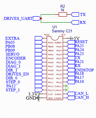
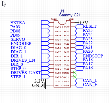
@pcr yes that should be possible. You could base the design on the Tool Board, but allocate two output pins for step and direction signals to the second driver, and an input pin for the DIAG output of the second driver. Two TMC2209 drivers can share the ENN pin and the UART pins.
The STEP pins for the two drivers should preferably be on the same port (A or B) because that is what RRF expects, so that it can achieve the highest step rates.
The TMC2209 has two pins that select the slave address. You should tie them to Vcc and ground so as to give the two drivers addresses 0 and 1.
-
This is brilliant. I am in the process of printing everything and waiting for my kit to show up to put it together. Nice work!
-
On a side note, why have settings.g and globals.g? Why not just use globals.g?
-
@alex-cr I prefer to make it so that there are some sane defaults and users can modify only what is necessary in settings, less clutter for the user to look at.
That's not to say that a user cannot edit globals.g and must edit settings.g -- one could completely ignore settings.g; but I feel it's a disservice to do so. One would have to repeat the setting twice (the initial declaration is guarded by
if exists) and that adds to clutter.The only inelegance of this approach is the selector_slotX_pos problem that requires a user to edit globals.g to remove slots if using a 4 cart system
-
-
@pcr you need both a Tx (normally Pad 0) pin and a Rx (any pad) pin on the same UART to control the TMC drivers. You've chosen to use PA12 for the Tx pin, so one option would be to use PA13 for the Rx pin and move STEP_1 to another PA pin. Or you could use PA20 and PA22 for the UART as we do on the tool board.
Another constraint is that every pin used as a digital input pin (including the two DIAG inputs from the TMC2209s) should be on a separate EXINT number.
You can choose whether to run the SAMC21 at 3.3V or 5V. The TMC2209s must use the same voltage on the VCCIO pin.
-
@pfn said in Adding support for the enraged rabbit carrot feeder (ERCF):
the kit I got has a less-than-straight D-shaft
I studied the build instructions and to me it seems, it's pretty easy to bend the D-shaft during assembly.
There are some points were it can go wrong.- Wrong height of the center bearing support
- Wrong length of the smooth rod assembly
- or just from handling the lower assembly without the top assembly
-
@o_lampe it's certainly a possibility that this is self inflicted. I already have 3 more rods on the way to help make sure it's less likely I end up with a bent rod if that's the case.
-
@pfn
I didn't want to blame you, but prepare for the new d-shaft. -
new demo video:
-
My tip forming isn't tuned yet, but at the moment it's a 10mm extrusion at 5mm/s, followed by unloading 80mm at 5mm/s; this part is actually really what takes longest
In regard to tip forming, I have been working on tuning this while my kit comes in.
Below is what is working for me in ABS so far if you are interested. I am using a Mosquito and LGX.;called to unload filament from the nozzle to support the ERCF G1 E4.0 F500 G1 E-10.0 F1500 G4 S1 G1 E-10.0 F300 G4 S1 G1 E-20.0 F700 G1 E-60.0 F1000 -
@o_lampe I think most of the stalling issues are related to poor dimensional accuracy/warping on my abs prints, I have no enclosure, so stuff isn't perfectly accurate.
-
It prints!

Still some issues to resolve:
cooling moves performed by superslicer immediately before changing filaments cause RRF to constantly flag that there's a filament-error: "tooLittleMovement" is detected. I don't know how to get around this yet. I'll try to generate a print job that replicates the cooling move and see how this triggers RRF into erroring.Errors during filament swapping while printing don't necessarily get handled well,
M98 R1doesn't seem to behave exactly as I expect, sometimes my macros appear to continue executing to the end (macroRestartedis false) and silently failing even though my full call stack hasM98 R1set.Some other tuning needs to be done around final filament parking and documenting how this could be used by more folks.
-

Just update the schmematic.
 I compeltly forgot about hte RX TX thign honestly. Last time i made a board wtih Stepper UART contoll it was the same mistake
