Solved: Fan control doesn't work correctly in RRF 3.3
-
Btw
If the bed is 65C then I will get 1600 rpm with this:M106 P3 H0 T20:40 L0.7 X254 C"Controller fan 2"I will get 6900 rpm (full rpm) with this:
M106 P3 H0 T20:40 L0.7 X255 C"Controller fan 2" -
As a manual fan I can control it
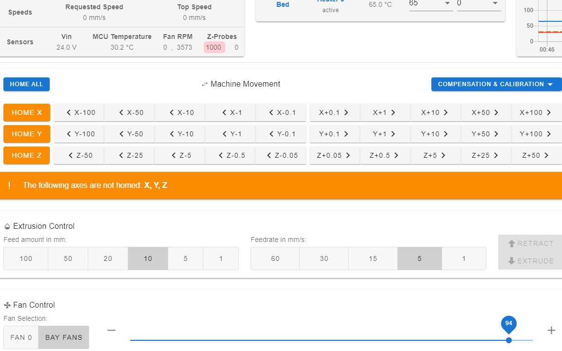
Also if I set one temp and set S0.95 I get half of full speed. But I can't seem to define a temp interval.
-
@gixxerfast which firmware version are you running? A bug in this area was fixed recently.
-
@dc42 V3.3 release I don't dare stepping into beta territory

m122 === Diagnostics === RepRapFirmware for Duet 3 Mini 5+ version 3.3 (2021-06-15 21:46:11) running on Duet 3 Mini5plus WiFi (standalone mode) Board ID: H1668-Y296U-D65J0-40KMA-KR03Z-RK6ZH -
@dc42
Are you thinking of this. It's a bit vague isn't it:In RepRapFirmware 3.4.0beta3
Bug fixes:

M106 proportional thermostatic control (i.e. using two T values) didn't work
It doesn't say when this bug was introduced and how it didn't work.
-
Something is wrong here. I adjust the fan in steps from the dashboard in DWC
; Controller fan 2
M950 F3 C"!0.out3+out3.tach" Q25000                     ; create fan 3 on pin out4 and set its frequency
;M106 P3 H0 L0.92 X0.98 T45:65 C"Controller fan 2"
M106 P3 S-1 C"Controller fan 2"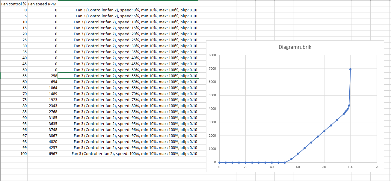
With temp control this get even stranger (and not really useful)
; Controller fan 2
M950 F3 C"!0.out3+out3.tach" Q25000                     ; create fan 3 on pin out4 and set its frequency
M106 P3 H0 L0.55 X1.0 T60:90 C"Controller fan 2"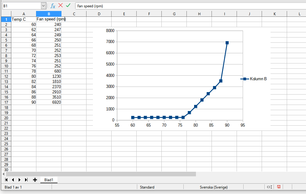
I get a clear feeling that if I multiply the values I put in fan control and multiply it by 1/255 then I'll get a value that corresponds approximately with the data sheet for the fan
-
Hi hope someone is reading these posts and can help
When looking in the object model I find this:
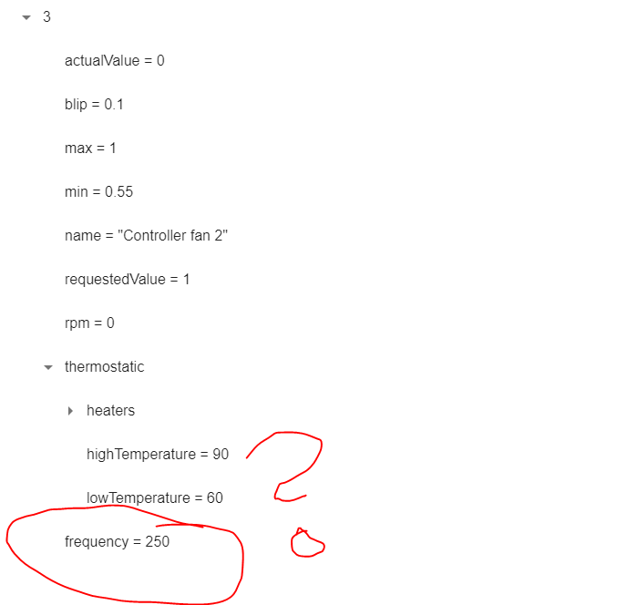
AFAIK, it should be 25000 Hz, what's going on here?
-
OK, I'm documenting here as I (sort of) understand what's going on.
In RRF 3.4 most aof the fan control that I seem to have issues with has been rewritten. The factor 0.5 that I sort get a hint of above seem to be have been totally removed.
So, the question is, do I dare to switch to RRF 3.4 beta or will I be in a heap of other troubles then?
-
@gixxerfast said in How do I control 4-wire fans:
With temp control this get even stranger (and not really useful)
Well, the shape of that graph is mostly correct for the config you've defined.
M106 P3 H0 L0.55 X1.0 T60:90
means run at 55% from 60C to 76.5C, then ramp up linearly to 100% at 90C. That's also (most of) what your graph shows teh behavior to be, given that your fan runs at 250rpm for a 55% signal.I agree that at 55% signal it should probably be running at faster than 250rpm, and it does't explain why you get a sudden jump in speed when you go from 99.6% to 100%.
However, all those behaviours would happen, I think, if the duet wasn't pulling the fan PWM line hard enough - if the PWM signal is ramping gradually and the fan is only seeing the very end of that ramp as being the relevant transition. So for short pulses (below about 50%, the fan doesn't see a transition at all, for longer pulses it only sees half the duration it should, but when it's a true 100% PWM, it sees all 100% of that. Seems to fit the symptoms (at least, it does to my naive level of electronics understanding).
I don't suppose you can lay your hands on an oscilloscope...?
Edit: if it is this (ie a hardware issue) switching to differnet firmware probably doesn't solve it.
-
@achrn No, I wish I had an oscilloscope though.
Yeah, the inclination of the curve is possibly correct but It's been shifted in x it seems to me.
In the object model the frequency is set to 250 though the config is correct, It should be 25000 I guess. Also I checked the fan controller code on giyhub and it has been been rewritten a lot in 3.4 so it might be a firmware issue in 3.3. Maybe people don't run four or three wire fans so much.
-
I had a look in LocalFan.cpp for 3.3 and it was pretty obvious that the old code was not correct and this has been changed in 3.4.
I therefore installed 3.4 beta 5 and yes, now the thermostatic control of a fan scales correctly to the interval that's configured.
However it's still strange that you have no fan rpm below 55% duty cycle and the difference between 99% and 100% duty cycle is 2700 rpm which is half of the max speed. It should IMO scale like the speed characteristics diagram above. Something should be corrected or explained here.
-
@gixxerfast said in Fan control doesn't work correctly in RRF 3.3 and and 3.4:
However it's still strange that you have no fan rpm below 55% duty cycle and the difference between 99% and 100% duty cycle is 2700 rpm which is half of the max speed. It should IMO scale like the speed characteristics diagram above. Something should be corrected or explained here.
That still sounds like a hardware fault to me - if something is stopping the signal pulling up fast enough (if pullup is too weak) it would happen like that, I think.
I think it's unlikely that so few people are using 4-pin fans that no-one else has noticed a catastrophic bug in the firmware..
As a data point, my delta (runing 3.3 firmware) has two 4-pin fans (Noctua Redux 1800) and they work as expected:
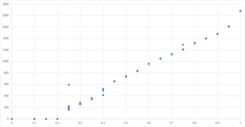
This is rpm v. duty, stepping from 0.1 duty up to 1.0 and back down to 0.0, in steps of 0.05, sampling the rpm ten times at 2 second intervals at each duty value each direction. There's one erratic data point at 0.25 duty on the way up, one at 0.75 on the way down. There's an interesting step (and some uncertainty) at 0.4 duty.
The raw data is here, the columns being time, requested duty, actual duty, rpm. fan4.txt
-
@achrn OK, thanks. How does you fan config look like? Do you have a pullup on the tacho signal ? Should that matter?
-
@gixxerfast said in Fan control doesn't work correctly in RRF 3.3 and and 3.4:
@achrn OK, thanks. How does you fan config look like? Do you have a pullup on the tacho signal ? Should that matter?
My config looks the same as yours:
M950 F4 C"!out5+out5.tach" Q25000(for purpose of this test, at least)I don't have any hardware mods - just four-pin fan connector plugged onto four-pin fan header. That is, take fan out of manufacturers packaging, plug it in to duet. Mine is a MB6HC.
Adding pullup to the tacho shouldn't be relevant, I think. That won't affect how fast the fan spins. (Unless you think your fan is actually spinning as fast as it should be, and it's just reporting low while spinning at the correct speed, but that wasn't the impression I got).
Pullup on the PWM might help. I hesitate to suggest a value (because I don't want to be responsible for frying your board or your fan) but maybe someone who is more confident about the circuits will chip in - https://forum.duet3d.com/post/251107 suggests an additional pullup of 10k to 5V. (If the fan is following the usual Intel spec 5V is the correct level - the Intel spec says 5.25V max).
-
@gixxerfast there appear to be three issues here:
-
The bug with fan temperature control over an interval, which has been fixed in RRF 3,4beta.
-
The object model browser in DWC always reports the fan PWM frequency as 250. This is because RRF does not report the PWM frequency. It appears that in the absence of receiving the frequency, DWC is displaying the default value instead of not displaying a value. I will change RRF to report the PWM frequency in the next beta.
-
Your fans do not provide a speed that scales linearly with the commanded PWM. This could be just the way your fans behave, or it could be an issue with PWM generation. To investigate the possibility of incorrect PWM generation, I connected a Noctua PWM fan to OUT3 on a Diet 3 Mini, configured it using m950 f5 c"!out3+out3.tach" q25000 and tried various fan settings. I also checked the PWM frequency, which was 24.999kHz according to my oscilloscope. The RPMs I read are:
20% 470
40% 1600
60% 2730
80% 3730
100% 5020So it appear to me to be working correctly. This was with firmware 3.4.0beta5.
-
-
PS - it's occurred to me that depending on the input circuit of your fan, you may be able to improve the response by connecting a pullup resistor between the PWM input and +5V. 10K would be a good starting point.
-
@dc42 OK, but the control pulse voltage is already 5V from the Duet? What would a pullup resistor do in this case?
I'm unfortunately a bit lacking in my knowledge of electronics.
-
@gixxerfast the output is open drain so it relies on there being a pullup resistor in the fan.
-
@dc42
Yes, that was (sorry for choice of words) bloody perfect. I added a pullup resistor as you said 10K and now they scale very well I have no gap between 99 - 100 % It won't run until 15% but that's sort of expected and not a problem.
Btw, I had 4.87V without the pullup between V- and control.
It's crimping time.

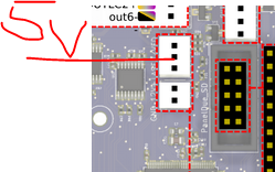
I hope I can take the 5v from here without any worries.
-
@gixxerfast thanks for confirming that.
The Intel specification for PWM fans says in section 2.1.4:
The following requirements are measured at the PWM (control) pin of the fan cable connector see Figure 7 and Table 1:
PWM Frequency: Target frequency 25 kHz, acceptable operational range 21 kHz to 28 kHz
Maximum voltage for logic low: VIL = 0.8 V
Absolute maximum current sourced: Imax = 5 mA (short circuit current)
Absolute maximum voltage level: VMax = 5.25 V (open circuit voltage)
This signal must be pulled up to a maximum of 5.25V within the fan.
Note:New fan designs are strongly encouraged to implement a 3.3V pull up for compatibility with buffer design limits on Hardware Monitor Devices e.g. Super IO devices.So the specification requires there to be a pullup resistor inside the fan, although it doesn't specify a maximum value for it (the maximum current sourced implies a minimum value of about 1K). My guess is that your fans have a pullup resistor with a very high value, so that in conjunction with the capacitance of the cable, it slows down the rise time of the PWM signal excessively. If the fan cable is long, that would make this more of a problem, due to the increased capacitance.