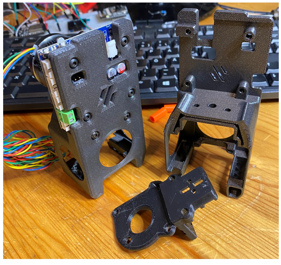
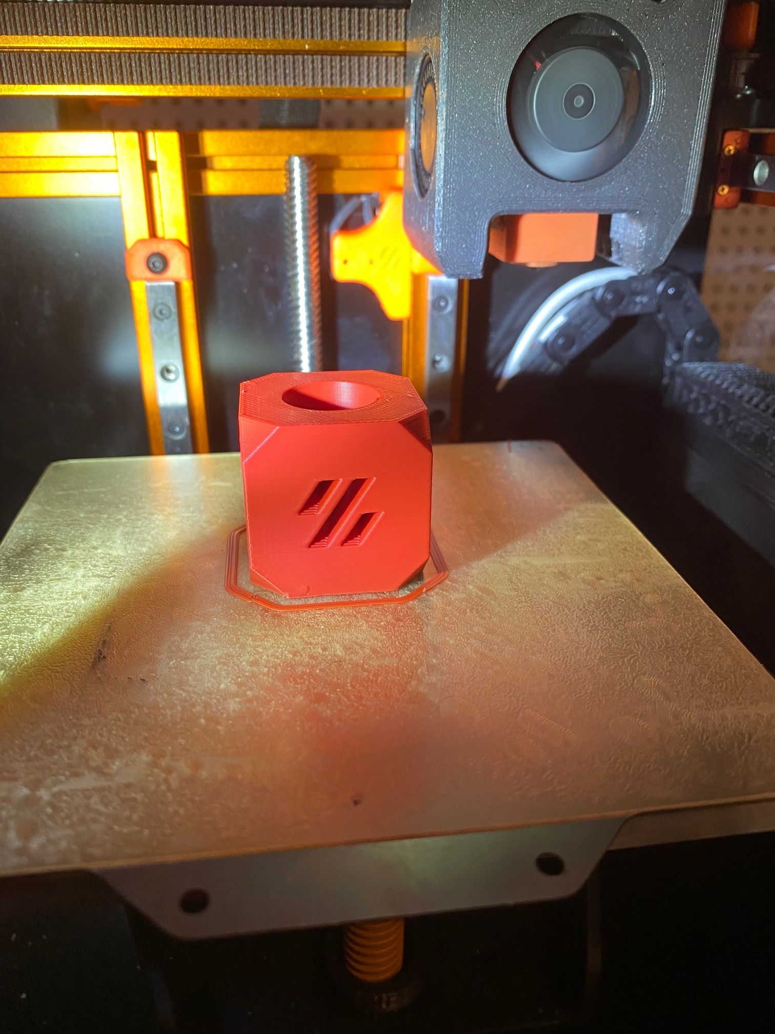
I got a question about my Voron V0.1 and the 1LC toolboard. There's really no room so I made this ugly looking thing which is a modified Bondtech Olof Ogland Cowling and mount. The only place I could place it was in front of the LGX Lite extruder. So here it is the 2001: A Space Odyssey monolith's ugly brother
Gixxerfast
@Gixxerfast
Nerd. (re-)Builds more than prints
Best posts made by Gixxerfast
-
Voron V0.1 1LC Toolboard mount
-
Canned ERCF board v1.0-beta2
So, the latest beta version of the Canned ERCF expansion board is back from JLCPCB and is ready. It seems to work fine though I'm in the middle of building the actual ERCF
It will require some more testing to be sure that there are no major flaws left.
The main differences to the first version is:
- Added a 4.7Kohms pullup resistor on the TX/RX UART line to keep the line high when Duet firmware momentarily disables UART when reading and transmitting. This can be handled with software changes but that will make maintenance harder as there will be more code to keep up to date.
- Added a 480 ohms series resistor on the io0.out PWM pin (to the servo)
- Added over voltage protection (up to 30V) to the io1.in, io2.in and io3.in inputs
- Added VIN voltage monitoring.
- Added separate CAN connectors to make it easier to hook it in the middle between the board and for example a toolboard.
I have made a fork of the Duet3Expansion firmware here which with the changes above only required changes to the SammyC21.h configuration file.
There is some history regarding this board in this thread.
-
RE: Schrodinger's Parameters
@theolodian Use a small i instead of the capital I in if
-
RE: Self calibrating Z offset implementation
@joeprint Do you mean like the Auto Z calibration ( https://github.com/protoloft/klipper_z_calibration )?
EDIT: Didn't see the link first.
Yes, I have a version of it. Take a look here: https://github.com/gixxerfast/rrf-voron2/tree/master/macros/autoz
It takes some adapting to get it to work so it's not quite plug and play. And there might be better ways of doing it ...
-
RE: BL Touch not working
Which version of RRF are you using, ver 2? I can't see that you've mentioned it.
EDIT: OK, so you're using RRF 3.3
Then I think you should config the BLTouch differently:
Have you read this bit, "Software setup (RepRapFirmware 3)" for the https://duet3d.dozuki.com/Wiki/Connecting_a_Z_probe
Either I'm a sloppy reader or I can't see that you have the M950
AS in this example:
2. Create a GPIO/Servo pin index using your chosen control pin, for example:M950 S0 C"io7.out" ; Duet 3 MB6HC
M950 S0 C"io3.out" ; Duet 3 Mini 5+
M950 S0 C"exp.heater3" ; Duet 2 WiFi/Ethernet
M950 S0 C"duex.pwm1" ; Duet 2 WiFi/Ethernet + DueX2/5
M950 S0 C"!exp.heater6" ; Duet 2 WiFi/Ethernet + BoB
M950 S0 C"zprobe.mod" ; Duet 2 Maestro -
RE: BLTouch issue Duet 3 Mini
@asimitabi To me it looks like you have it connected to io4.
Or am I looking at the wrong picture ?
-
Sammy C21 support for 2 TMC2209 drivers with UART com
Hi,
I'm tinkering with a little project where I'm using the Sammy C21 and I want to enable support for two TMC2209 drivers with serial communication/configuration.It was fairly straightforward to modify the Sammy C21 firmware so that I can have two drivers with step/dir control. However when I want to enable UART/sercom things get a bit more complicated.
Part of it is probably because I don't know what I'm doing
These are the defines I'm using at the moment
#define BOARD_TYPE_NAME "SAMMYC21" #define BOOTLOADER_NAME "SAMMYC21" // General features #define HAS_VREF_MONITOR 0 // Nope no VREF-monitor #define HAS_VOLTAGE_MONITOR 0 // Nope, this wil break the build! #define HAS_12V_MONITOR 0 #define HAS_CPU_TEMP_SENSOR 1 #define HAS_ADDRESS_SWITCHES 0 // What is this? #define HAS_BUTTONS 0 // Nope // Drivers configuration #define SUPPORT_DRIVERS 1 #define HAS_SMART_DRIVERS 1 #define HAS_STALL_DETECT 0 #define SINGLE_DRIVER 0 // UE #define SUPPORT_SLOW_DRIVERS 0 // UE #define SUPPORT_DELTA_MOVEMENT 0 #define USE_EVEN_STEPS 0 // UE //------------------------------------------------------------------ #define ACTIVE_HIGH_STEP 1 // 1 = active high, 0 = active low #define ACTIVE_HIGH_DIR 0 // 1 = active high, 0 = active low #define SUPPORT_TMC51xx 0 #define SUPPORT_TMC2160 0 #define SUPPORT_TMC2660 0 #define SUPPORT_TMC22xx 1 constexpr size_t NumDrivers = 2; constexpr size_t NumSmartDrivers = NumDrivers; constexpr size_t MaxSmartDrivers = NumDrivers; #define TMC22xx_USES_SERCOM 1 // UE #define TMC22xx_HAS_MUX 1 // I don't have a MUX but if I set this everything gets easier it seems #define TMC22xx_SINGLE_DRIVER 0 // UE #define TMC22xx_HAS_ENABLE_PINS 0 // <- Am I supposed to set this ? #define TMC22xx_VARIABLE_NUM_DRIVERS 0 // No, it's fixed to two #define TMC22xx_USE_SLAVEADDR 1 // What does this mean ? #define TMC22xx_DEFAULT_STEALTHCHOP 0 // No thanks constexpr Pin GlobalTmc22xxEnablePin = PortAPin(9); constexpr uint8_t TMC22xxSercomNumber = 4; Sercom * const SERCOM_TMC22xx = SERCOM4; //Sercom * TMC22xxSercoms[NumDrivers] = {SERCOM3, SERCOM3}; constexpr Pin TMC22xxSercomTxPin = PortAPin(22); constexpr GpioPinFunction TMC22xxSercomTxPinPeriphMode = GpioPinFunction::C; constexpr Pin TMC22xxSercomRxPin = PortAPin(20); constexpr GpioPinFunction TMC22xxSercomRxPinPeriphMode = GpioPinFunction::D; constexpr uint8_t TMC22xxSercomRxPad = 2;
Does the defines above look right for a simple TMC2209 board?
I now have a few build errors left
../src/Platform.cpp: In function 'void Platform::Spin()': ../src/Platform.cpp:983:21: error: 'powered' was not declared in this scope 983 | SmartDrivers::Spin(powered); | ^~~~~~~ ../src/Platform.cpp: In function 'void Platform::SetOrResetEventOnStall(DriversBitmap, bool)': ../src/Platform.cpp:1814:3: error: 'eventOnStallDrivers' was not declared in this scope 1814 | eventOnStallDrivers |= drivers; | ^~~~~~~~~~~~~~~~~~~ ../src/Platform.cpp:1818:3: error: 'eventOnStallDrivers' was not declared in this scope 1818 | eventOnStallDrivers &= ~drivers; | ^~~~~~~~~~~~~~~~~~~ src/subdir.mk:24: recipe for target 'src/Platform.o' failed
The first is because I don't have a voltage monitoring so the variable is never defined.
The second is about the same but for stallguard.As you can see I'm testing my way forward
I know that you guys have probably a lot of more urgent things to handle but I would appreciate a nudge in the right direction if possible.
-
RE: Comparing klipper and RRF input shaper data collection
@gloomyandy
So. I assume this is the current standalone version of Andys script (with spaces instead of tabs ) Thanks again!var title = "Klipper style vibration test V0.3" var axis="Y" var datarate=1320 var stime = state.upTime var min_freq = 5.0 var max_freq = 10000/75 var accel_per_hz = 75 var hz_per_sec = 1 var freq = var.min_freq var max_accel = var.max_freq * var.accel_per_hz var X = 150.0 var Y = 150.0 var sign = 1.0 var t_seg = 0 var accel = 0 var max_v = 0 var L = 0 var nX = 0 var old_freq = 0 var filename = "/gcodes/vtest_" ^ var.axis ^ ".gcode" echo "max_accel " ^ var.max_accel ^ " min freq " ^ var.min_freq ^ " max freq " ^ var.max_freq echo >{var.filename} " " echo >>{var.filename} "M201 X" ^ var.max_accel ^ " Y" ^ var.max_accel echo >>{var.filename} "M205 X0 Y0" echo >>{var.filename} "G91" echo >>{var.filename} "M400" echo >>{var.filename} "G4 S1" echo >>{var.filename} "M956 P0 A0 S" ^ (var.max_freq - var.min_freq) * var.datarate * var.hz_per_sec echo "Testing " ^ floor(var.freq) echo >>{var.filename} "echo " ^ var.freq while var.freq < var.max_freq + 0.000001 set var.t_seg = 0.25 / var.freq set var.accel = var.accel_per_hz * var.freq set var.max_v = var.accel * var.t_seg echo >>{var.filename} "M204 P" ^ var.accel ^ " T" ^ var.accel set var.L = 0.5 * var.accel * (var.t_seg*var.t_seg) set var.nX = (var.sign * var.L) echo >>{var.filename} "G1 " ^ var.axis ^ var.nX ^ " F" ^ var.max_v*60 echo >>{var.filename} "G1 " ^ var.axis ^ -var.nX set var.sign = -var.sign set var.old_freq = var.freq set var.freq = var.freq + (2. * var.t_seg * var.hz_per_sec) if floor(var.freq) > floor(var.old_freq) ;echo >> var.filename "echo " ^ floor(var.freq) echo "Testing " ^ floor(var.freq) echo >>{var.filename} "G90" echo "total time " ^ state.upTime - var.stime
-
RE: Euclid probe kit with hardware in EU?
@zapta said in Euclid probe kit with hardware in EU?:
this is very useful. Where can I find the STL models?
https://github.com/nionio6915/Euclid_Probe/tree/main/stls/Voron
Think (probably) I used VoronGantryMount2_Bkt.stl and VoronGantryMount2NativeCarriage.stl
They could be optimized further but works fine as is for me.
-
RE: Y Homing on CoreXY
OK, I have a 2.4 as well and even though mine isn't a standard setup I home it on max (300, 305) in the top right corner.
I see two things when looking quickly:
- In the homey.g you go relative +360mm and then back up by trying to go relative +5 mm if I read it correctly?
- I have a pullup on my switches
; Endstops M574 X2 S1 P"^121.io0.in" M574 Y2 S1 P"^0.io1.in" M574 Z0 p"nil"
Latest posts made by Gixxerfast
-
RE: Z-drives not moving, new Duet3
@heide Hi, if you're using the hall effect sensor in its default location, may I ask why you define your X and Y endstops to be low end?
Normally on a Voron, the X0 and Y0 is front left corner of the bed. And you home at max X and Y.
Here's my endstop configuration:
; Endstops M574 X2 S1 P"121.io0.in" ; configure active-high endstop for high end on X via pin 121.io0.in M574 Y2 S1 P"0.io1.in" ; configure active-high endstop for high end on Y via pin io1.in
However, I do not use the hall effect, but that's just an inverse away.
Also, a simple M119 will tell you all you need to know, one where they should be activated and one where they should not be.
-
RE: BLTouch issue Duet 3 Mini
@asimitabi
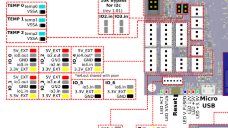
Also make sure to have a look in here (or newer docs preferably)// https://duet3d.dozuki.com/Wiki/Duet_3_Mini_5plus_Hardware_overview#Section_IO_port_pin_capabilities
https://docs.duet3d.com/Duet3D_hardware/Duet_3_family/Duet_3_Mini_5+_Hardware_Overview
I guess you want the pwm capability.
-
RE: BLTouch issue Duet 3 Mini
@asimitabi To me it looks like you have it connected to io4.
Or am I looking at the wrong picture ?
-
RE: Voron 2.4 Z movement one motor out of sync
@kleslietx It's not unheard of that people have managed to use the wrong size pulley in the Z gearbox. Worth a check maybe.
-
RE: Some advice for my Endstops
@tim-c Without knowing for sure since I do not not own such a printer, a little bit of googling suggests that these are 12-24V NPN inductive sensors which means that they require at least 12V to work reliably.
Have a look in this old thread: https://forum.duet3d.com/topic/12056/npn-12v-endstops-at-duet-wifi
If this is correct, it will behave as my old PL-08N2 inductive probe and output near input voltage when near a metal object. Just make sure that your input port can handle the higher (>3.3V signal) voltage.
-
RE: Low voltage on Duet3 6CH IO pins
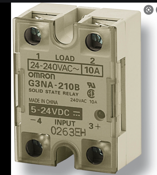
@e4d May I ask which SSR you are using as many, for example, Omrons are speced to at least 5V to switch.
Example:
-
RE: Canned ERCF board v1.0-beta2
Apologizes to those who contacted me about the board, I have been (and still am) a wee bit under the weather but I'll respond to you shortly.
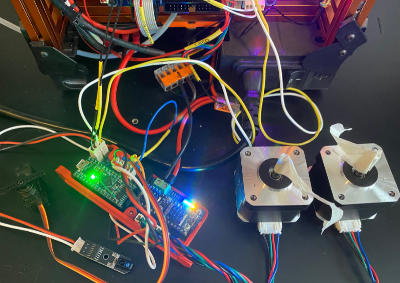
Anyway, I thought that a good test for the board would be to hook it up to drive the A & B motors on the Voron V0.1 running two Nema 14 motors at 1200 mA at 4000 mm/s^2 (5000 travel) and see what happens.
Said and done. Start:
https://youtu.be/Jh0_QzTjQ-QEnd:
https://youtu.be/QYoGkQ9I5lcFinished test print:
With this I'm pretty sure it will ahev no problems winding some filaments up and down with th ERCF
Btw, the enraged rabbit feeder is on the way
I have another new version in mind that utilizes more Duet hardware but it requires more changes to the firmware changing the slave addressing. Shouldn't be more that a few places. Maybe a couple of ifdefs is enough
I just love the Duet hardware and RRF. Swap two drive cables. change two lines in the config.g and restart and you have swapped motor drivers to another board.
-
RE: Canned ERCF board v1.0-beta2
@r4ffers Well, I have some extra boards to sell. The tricky part is to get hold of a Sammy. the ATSAMC21 is a bit unobtanium at the moment (for us regular folks anyway)
-
Canned ERCF board v1.0-beta2
So, the latest beta version of the Canned ERCF expansion board is back from JLCPCB and is ready. It seems to work fine though I'm in the middle of building the actual ERCF
It will require some more testing to be sure that there are no major flaws left.
The main differences to the first version is:
- Added a 4.7Kohms pullup resistor on the TX/RX UART line to keep the line high when Duet firmware momentarily disables UART when reading and transmitting. This can be handled with software changes but that will make maintenance harder as there will be more code to keep up to date.
- Added a 480 ohms series resistor on the io0.out PWM pin (to the servo)
- Added over voltage protection (up to 30V) to the io1.in, io2.in and io3.in inputs
- Added VIN voltage monitoring.
- Added separate CAN connectors to make it easier to hook it in the middle between the board and for example a toolboard.
I have made a fork of the Duet3Expansion firmware here which with the changes above only required changes to the SammyC21.h configuration file.
There is some history regarding this board in this thread.
-
RE: FAN 0 & FAN 1 allways ON
@phaedrux It's from here as far as I can see: https://duet3d.dozuki.com/Wiki/M106
But can you really refer to it via number >=100 in the H parameter ?
I see nothing that implies that.
OK, so with RRF V3 you cannot use +100 to refer to the MCU or other sensor (virtual heater) as I initally wrote far above here somewhere.