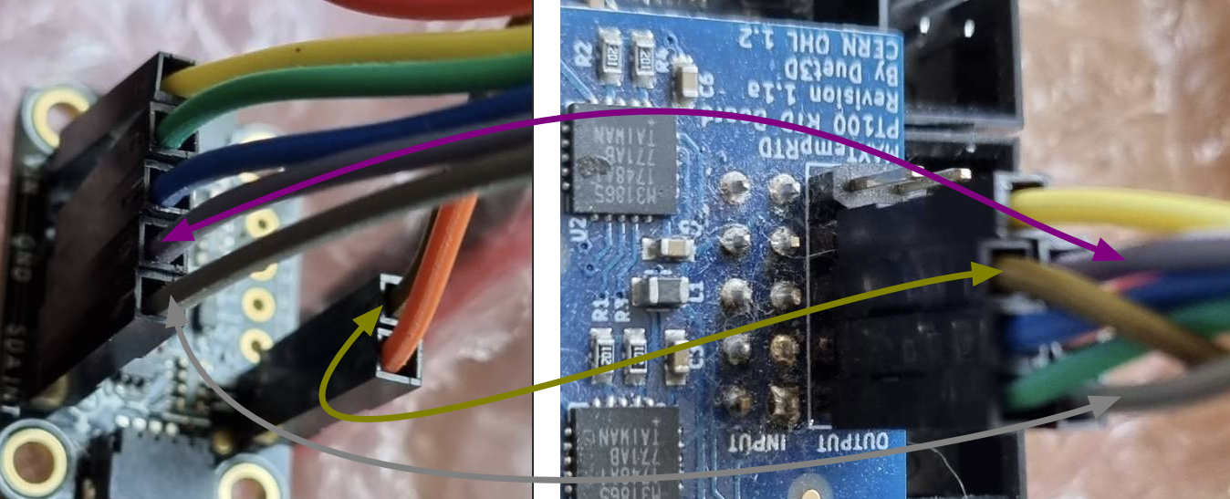
Accelerometer Usage
-
@ccs86 I'll try that configuration here.
-
@ccs86 this arrangement is working for me, using the following command:
m955 p0 c"twck0+twd0"
I tried without enabling the PT100 channels, and also after enabling both channels. I normally connect the 3.3V wire to the 3.3V pin on the accelerometer, but I tried connecting it to the accelerometer VIN pin to match your setup, and it still works.


-
-
@ccs86 yes, the wiring is as you have indicated.
-
@dc42 said in Accelerometer Usage:
@ccs86 yes, the wiring is as you have indicated.
Thanks for sticking with me, I finally got it working! Not sure if it had more to do with connecting to both the main board and the daughterboard, or if I had made an error somewhere.
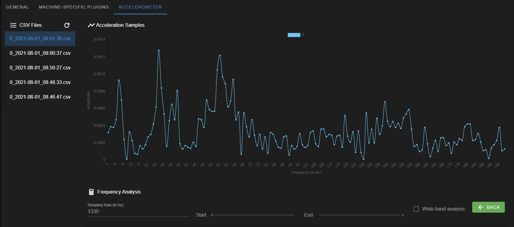
I am running into quite a few overflow errors now, but don't see the rhyme or reason. Reducing the collection call to one axis and 500 samples still reported overflows. But after adding the S parameter to the M955 command, I got it to log all 3 axis for 1000 samples without an issue. That M955 S parameter behaves differently than I expected:
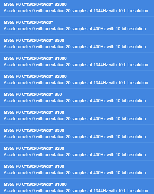
Sometimes I get overflow errors at 400 Hz, but not at 1344 Hz
-
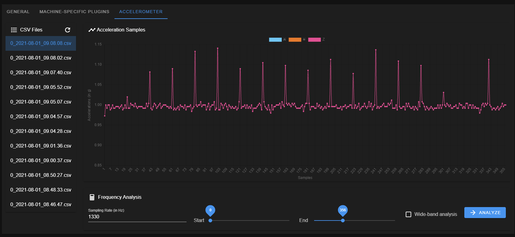
Also, is there anything I can do to reduce apparent noise in the accelerometer signal? These peaks seem like anomolies. This is with the printer at rest and steppers disabled. The peaks look very periodic.
-
@ccs86 could those peaks be from your fan?
-
About the overflows - I was getting these at first. Turned out the write speed of my SD card was abysmal (0.8MB/s). I got a new SD card and all is good now.
Try running an SD read/write test ( M122 P104 S[file size in MB] ) and get a new card if write speeds are under 1.5MB/s
-
@ajdtreyd said in Accelerometer Usage:
About the overflows - I was getting these at first. Turned out the write speed of my SD card was abysmal (0.8MB/s). I got a new SD card and all is good now.
Try running an SD read/write test ( M122 P104 S[file size in MB] ) and get a new card if write speeds are under 1.5MB/s
Good call!
Not terrible, not amazing:
SD write speed for 5.0Mbyte file was 1.95Mbytes/secI'll probably pop a new one in for good measure,
-
@t3p3tony said in Accelerometer Usage:
@ccs86 could those peaks be from your fan?
All fans were off during this test.
Interestingly, every single one of these peaks falls on an even 20 sample interval (#20, #40, #60, #80, #100, #120, etc).
There are a few places (like #320) where the value appears normal.
1330 Hz / 20 = 66.5 Hz. I'm not sure if that frequency coincides with anything computational on the main board.
-
@ccs86
All the time reading about the accel sensorboard, I was worried about feeding the Vin pin with 3.3V.
The sensorboard sure uses an LowDrop voltage regulator, but does it work reliable with such low voltage?
@dc42 uses the 3V (out) pin to feed 3.3V backwards into the board, which makes more sense to me.Maybe worth trying to either feed 5V through Vin or in Davids way and repeat the test.
-
@o_lampe said in Accelerometer Usage:
@ccs86
All the time reading about the accel sensorboard, I was worried about feeding the Vin pin with 3.3V.
The sensorboard sure uses an LowDrop voltage regulator, but does it work reliable with such low voltage?
@dc42 uses the 3V (out) pin to feed 3.3V backwards into the board, which makes more sense to me.Maybe worth trying to either feed 5V through Vin or in Davids way and repeat the test.
They claim that this board will take a 3V-5V input. But, it's easy enough to test, so...
-
@ccs86 said in Accelerometer Usage:
Interestingly, every single one of these peaks falls on an even 20 sample interval (#20, #40, #60, #80, #100, #120, etc).
I suspect it may be an undetected data overrun then. RRF tries to read 20 values at a time. The FIFO in the accelerometer is 32 values long, so this allows some leeway. Try capturing all three axes and see if it is the same on all of them.
-
@dc42 said in Accelerometer Usage:
@ccs86 said in Accelerometer Usage:
Interestingly, every single one of these peaks falls on an even 20 sample interval (#20, #40, #60, #80, #100, #120, etc).
I suspect it may be an undetected data overrun then. RRF tries to read 20 values at a time. The FIFO in the accelerometer is 32 values long, so this allows some leeway. Try capturing all three axes and see if it is the same on all of them.
I can confirm that X and Y also have these 20-sample peaks.
-
@ccs86 what M955 and M956 parameters are you using? I will try the same parameters.
-
@dc42 said in Accelerometer Usage:
@ccs86 what M955 and M956 parameters are you using? I will try the same parameters.
M955 P0 C"twck0+twd0"G1 X25 G4 S2 G1 X125 F20000 M400 M956 X P0 S1000 A0 -
If you need to buy one, I can recommend the PNY EliteX U3 V30 64GB. It's getting 3.8-4Mb/s write speed in my Duet 2 Wifi.

-
@ccs86 I've run the accelerometer on my Maestro and the result is fairly clean:
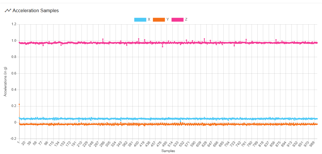
However, there are some small glitches on the Z reading and it looks like they may be at multiples of 20 samples. I'll try reading one less sample from the FIFO.
-
Reading one less sample doesn't help. I can only assume that communicating with the accelerometer creates an electrical disturbance that slightly affects the reading.
-
@dc42 said in Accelerometer Usage:
Reading one less sample doesn't help. I can only assume that communicating with the accelerometer creates an electrical disturbance that slightly affects the reading.
If you read only 10 samples at a time, do the peaks appear at that new interval?
