Heater and fans not working.
-
- Bed heater is shutting down, error to slow as it can not reach 1.7°C/s
Thermistor seems to be OK. This is quite big bed 400x400 on my Chiron. Isolated heater to get better heat spreading.
- Is there a way to change 1.7°C/s to slower value ?
- Have no fans working on out_5 and out_6. Out 3 works OK for the big Noctua fan cooling board/drivers.
out5-6 short at pins V_fused+ and V_outlc2
I am all ears on how to get these issues solved.
edit/ forgot
; Heaters
M308 S0 P"temp0" Y"thermistor" T100000 B4138 ; configure sensor 0 as thermistor on pin temp0
M950 H0 C"out1" T0 ; create bed heater output on out1 and map it to sensor 0
M307 H0 B0 S1.00 ; disable bang-bang mode for the bed heater and set PWM limit
M140 H0 ; map heated bed to heater 0
M143 H0 S120 ; set temperature limit for heater 0 to 120C
M308 S1 P"temp1" Y"thermistor" T100000 B4138 ; configure sensor 1 as thermistor on pin temp1
M950 H1 C"out2" T1 ; create nozzle heater output on out2 and map it to sensor 1
M307 H1 B0 S1.00 ; disable bang-bang mode for heater and set PWM limit
M143 H1 S280 ; set temperature limit for heater 1 to 280C; Fans
M950 F0 C"out5" Q500 ; create fan 0 on pin out5 and set its frequency
M106 P0 S0 H-1 ; set fan 0 value. Thermostatic control is turned off
M950 F1 C"out6" Q500 ; create fan 1 on pin out6 and set its frequency
M106 P1 S1 H1 T45 ; set fan 1 value. Thermostatic control is turned on
M950 F2 C"out3" Q500 ; create fan 2 on pin out3 and set its frequency
M106 P2 S1 H1 T45 ; set fan 2 value. Thermostatic control is turned on - Bed heater is shutting down, error to slow as it can not reach 1.7°C/s
-
- Your M307 commands are the default in your config.g. M307 defines the PID control of your heater. Tune your bed heater (and hot end heater) with M303, and update your config.g with the M307 result. See https://duet3d.dozuki.com/Wiki/Gcode#Section_M303_Run_heater_tuning and https://duet3d.dozuki.com/Wiki/Tuning_the_heater_temperature_control
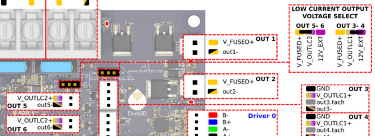
- I assume you have a Duet Mini 5+. It's best to post what hardware and firmware version you are using in your initial post. What voltage PSU are you using for VIN? How is the voltage selection jumper set? What voltage fan are you connecting? Check the fan polarity that you are connecting to out5 and out6; V_OUTLC2+ is positive, out5- is negative.
Ian
-
@tecno said in Heater and fans not working.:
Bed heater is shutting down, error to slow as it can not reach 1.7°C/s
Thermistor seems to be OK. This is quite big bed 400x400 on my Chiron. Isolated heater to get better heat spreading.Is there a way to change 1.7°C/s to slower value ?
-
This post is deleted! -
Bed heater now PID adjusted.
M307 H0 R0.209 C688.7 D1.31 S1.00 V24.2
-
console.txt
24V to 24.5V
out5-6 short at pins V_fused+ and V_outlc2
24V fans
Connected V_OUTLC2+ is positive, out5- is negative.
Fans verified working with 24V -
So my conclusion is that fan0 and fan1 outputs are dead. Nothing on pins.
What is next step? Received the board on Friday last week. Purchased via RepRapWorld Bart in Holland so is he handling this exchange ??
-
@tecno said in Heater and fans not working.:
out5-6 short at pins V_fused+ and V_outlc2
I'm not clear on your description of the fault. Are you saying that, when you put the jumper on the out5-6 voltage select, you get a short to ground?
Or do you mean you read no voltage between V_fused+ and V_outlc2 (which you won't)?
Or do you mean, with jumper between V_fused+ and V_outlc2 (on voltage select) you get no voltage between pin V_OUTLC2+ (on OUT 5 and OUT 6) and GND?
Have you checked the fuse?
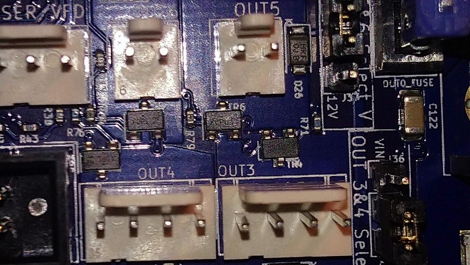
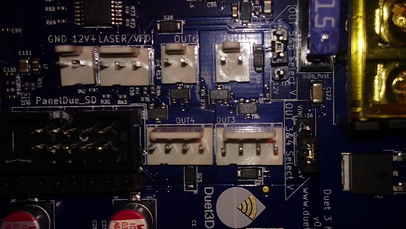
Otherwise, please post a picture of your board, particularly showing the condition of the components around OUT 5 and OUT 6, in case the MOSFETs are damaged.
Ian
-
@droftarts
Jumper on Vfuse and VoutYes I mean NO voltage out on out 5 and 6
M106 P0 S255 should give me close to full 24V
Nothing looks damaged! Been working with electronics for the last 40 years (now70+)
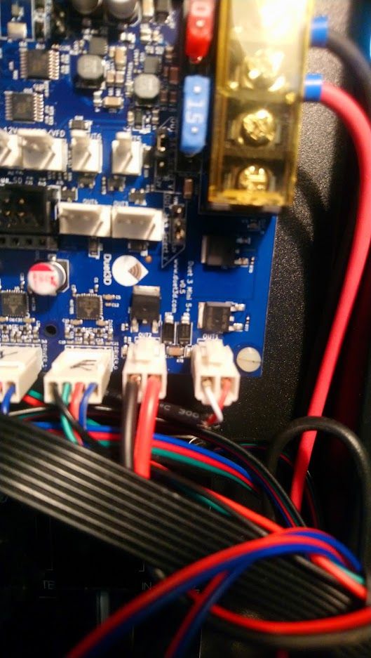
Below bad fast picture, need better lighting.
DSC_0708.JPG -
@tecno I can't really see much in the picture. Just so we are clear, the circuit goes like this:
VIN
10A inline fuse
V_fused+ (on OUT5 and OUT6 voltage selector pins)
V_outlc2 (on OUT5 and OUT6 voltage selector pins)
V_outlc2+ (on OUT5 and OUT6 pins)
(your fan wired between)
out5- (or out6-, on OUT5 and OUT6 pins)
MOSFET (switch)
GNDWith the fan disconnected, you should be able to read 24V between GND and each of VIN, 10A inline fuse (both sides), V_fused+, V_outlc2 and V_outlc2+. You will not read 24V between any of these and out5-, because the pin is switched by the MOSFET on the negative side. Please test where 24V is getting to; it might just be the jumper on the fan voltage select is not making contact, or one of the pins is not soldered on the back.
Ian
-
24V all the way to V_outlc2+ (on OUT5 and OUT6 pins)
So it must be MosFet's that are busted.
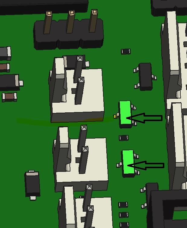
Also one thing that surprised me was board shipped with BETA FW
-
@tecno okay… just to check your config, and double check it’s not turning on:
M950 F0 C"out5" Q500 ; create fan 0 on pin out5 and set its frequency M106 P0 S0 H-1 ; set fan 0 value. Thermostatic control is turned off M950 F1 C"out6" Q500 ; create fan 1 on pin out6 and set its frequency M106 P1 S1 H1 T45 ; set fan 1 value. Thermostatic control is turned onFan 0 on Out5 is configured off at startup. Fan 1 is configured to turn on with heater H1, when it gets to 45C. You haven’t included tool definition, so just in case you have bound the fans to tool 0, send T0 (or whichever tool the are bound to) then send M106 P0 S1 H-1 and
M106 P1 S1 H-1. Both fans should turn on full.Ian
-
No luck, fans are dead

-
Looks like I have received a DOA board delivery

-
Does there appear to be any visible damage to the fan mosfets?
Would you be able to test the mosfets with a multimeter?
And just in case, have you confirmed that the fans themselves are working by connecting them to an always on fan header?
-
@phaedrux
As I wrote earlier no visible damage and fans verified with 24V
Yes, advise how
There is only 2 fan headers and both are dead. -
@tecno, please can you post a close-up photo of those two fan mosfets.
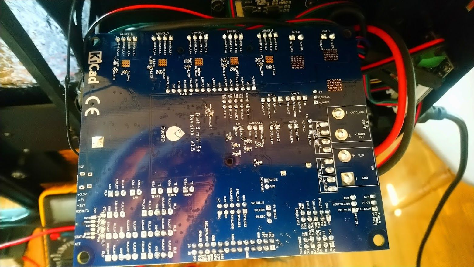
What revision number is the board? It's printed on the underside.
-
-
@tecno that’s perfect, thanks. I approve a warranty replacement. Please contact the seller and follow their warranty process, quoting this thread as authorisation. Apologies for the inconvenience.
Ian
-
