Upgrading Firmware.
-
I re-posted your config.g file using the </> tag:
; Configuration file for Duet WiFi (firmware version 3) ; executed by the firmware on start-up ; ; generated by RepRapFirmware Configuration Tool v3.2.3 on Thu Feb 25 2021 21:07:52 GMT+0100 (Central European Standard Time) ; General preferences G90 ; send absolute coordinates... M83 ; ...but relative extruder moves M550 P"MENDELEVIUM 3D HULK TWIN TOOLS" ; set printer name ; Network M552 S1 ; enable network M586 P0 S1 ; enable HTTP M586 P1 S0 ; disable FTP M586 P2 S0 ; disable Telnet ; Drives M569 P0 S1 ; physical drive 0 goes forwards M569 P1 S1 ; physical drive 1 goes forwards M569 P2 S1 ; physical drive 2 goes forwards M569 P3 S1 ; physical drive 3 goes forwards M569 P4 S1 ; physical drive 4 goes forwards M584 X0 Y1 Z2 E3:4 ; set drive mapping M350 X16 Y16 Z16 E16:16 I1 ; configure microstepping with interpolation M92 X80.00 Y80.00 Z400.00 E420.00:420.00 ; set steps per mm M566 X900.00 Y900.00 Z60.00 E120.00:120.00 ; set maximum instantaneous speed changes (mm/min) M203 X6000.00 Y6000.00 Z180.00 E1200.00:1200.00 ; set maximum speeds (mm/min) M201 X500.00 Y500.00 Z20.00 E250.00:250.00 ; set accelerations (mm/s^2) M906 X800 Y800 Z800 E800:800 I30 ; set motor currents (mA) and motor idle factor in per cent M84 S30 ; Set idle timeout ; Axis Limits M208 X0 Y0 Z0 S1 ; set axis minima M208 X325 Y300 Z280 S0 ; set axis maxima ; Endstops M574 X2 S1 P"xstop" ; configure active-high endstop for high end on X via pin xstop M574 Y1 S1 P"ystop" ; configure active-high endstop for low end on Y via pin ystop M574 Z2 S1 P"zstop" ; configure active-high endstop for high end on Z via pin zstop ; Z-Probe M558 P0 H5 F120 T6000 ; disable Z probe but set dive height, probe speed and travel speed M557 X15:215 Y15:195 S20 ; define mesh grid ; Heaters M308 S0 P"bedtemp" Y"thermistor" T100000 B4138 ; configure sensor 0 as thermistor on pin bedtemp M950 H0 C"bedheat" T0 ; create bed heater output on bedheat and map it to sensor 0 M307 H0 B1 S1.00 ; enable bang-bang mode for the bed heater and set PWM limit M140 H0 ; map heated bed to heater 0 M143 H0 S120 ; set temperature limit for heater 0 to 120C M308 S1 P"e0temp" Y"thermistor" T100000 B4138 ; configure sensor 1 as thermistor on pin e0temp M950 H1 C"e0heat" T1 ; create nozzle heater output on e0heat and map it to sensor 1 M307 H1 B0 S1.00 ; disable bang-bang mode for heater and set PWM limit M143 H1 S280 ; set temperature limit for heater 1 to 280C M308 S2 P"e1temp" Y"thermistor" T100000 B4138 ; configure sensor 2 as thermistor on pin e1temp M950 H2 C"e1heat" T2 ; create nozzle heater output on e1heat and map it to sensor 2 M307 H2 B0 S1.00 ; disable bang-bang mode for heater and set PWM limit M143 H2 S280 ; set temperature limit for heater 2 to 280C ; Fans M950 F0 C"fan0" Q500 ; create fan 0 on pin fan0 and set its frequency M106 P0 S0 H-1 ; set fan 0 value. Thermostatic control is turned off M950 F1 C"fan1" Q500 ; create fan 1 on pin fan1 and set its frequency M106 P1 S1 H-1 ; set fan 1 value. Thermostatic control is turned off ; Tools M563 P0 S"EXTRUDER 0" D0 H1 F0 ; define tool 0 G10 P0 X-16.5 Y0 Z0 ; set tool 0 axis offsets G10 P0 R0 S0 ; set initial tool 0 active and standby temperatures to 0C M563 P1 S"EXTRUDER 1" D1 H2 F0 ; define tool 1 G10 P1 X16.5 Y0 Z0 ; set tool 1 axis offsets G10 P1 R0 S0 ; set initial tool 1 active and standby temperatures to 0C ; Custom settings are not defined ; Miscellaneous M575 P1 S1 B57600 ; enable support for PanelDue M911 S10 R11 P"M913 X0 Y0 G91 M83 G1 Z3 E-5 F1000" ; set voltage thresholds and actions to run on power loss -
@mendelevium said in Upgrading Firmware.:
When I had the ver 2 firmware the system has a test and when I tested the motors, it went on to test the Z, X and Y together with the 2 extruder motors. The new ver 3 software simply tests X Y and Z..
What exactly do you mean by "the system has a test" - was this something you coded?
Frederick
-
your thermistor setting is incorrect. b4138 is the default. look up the correct beta value in your thermistor documentation.
-
@fcwilt
when the duet is switched on the panel due has a test motors button... -
@mendelevium and what does that button look like as I have never ever seen a test motors button before and I have been using it from the very early days of the Duet WiFi and the panel from before then.
-
-
@mendelevium DON'T use the test macros; they're for factory testing, and change the motor settings. Reset your Duet and follow the documentation for testing.
Longer explanation: Did you run '04-Test_motors' macro? The macros on the SD card are for testing the Duet at the factory, not for testing your machine. It sets the motor to 2A, as well as trying to move the axes at high speed, and for 2 metres! In the test rig at the factory, it is just a motor, not connected. So please DO NOT USE the macros on the SD card for testing your machine. Follow the commissioning advice here: https://duet3d.dozuki.com/Wiki/Step_by_step_guide#Section_Commissioning_tests
If you have these macros on the SD card, this also means you have an older board, as we changed the SD card contents to remove these macros quite a while ago.
-
To be honest, I am still testing this printer as I have migrated from ramps.. still my extruder is not running. The extruder buttons on the web console are mot highlighted and unresponsive.
-
@droftarts thanks for this I will go through it...
-
@fcwilt said in Upgrading Firmware.:
M563 P1 S"EXTRUDER 1" D1 H2 F0 ; define tool 1
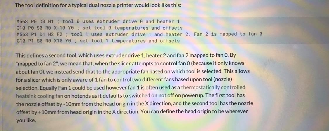
If you have a separate fan for each tool, then your second tool should probably be using fan1. Change the F0 to F1.
@fcwilt said in Upgrading Firmware.:
G10 P0 X-16.5 Y0 Z0 ; set tool 0 axis offsets
I'm not a multi tool printer users, but I think it's usually the case that the first tool is set as a zero offset and the other tools are then offset from there. Just keeps things easier.
-
You replied to me because I reposted his config.g using the </> tag.
I don't know if he will be notified of your post or not.
Frederick
-
I will go through the tests and see. This is my first twin extruder machine I built. I had very little experience. This printer I have installed Mechaduinos on X & Y. I have soldered STEP AND DIR POINTS on the test points on the board. The mechaduinos I have set the PID settings when it ran Ramps, so I am assuming the PID`s are ok with the duet in use. I have arranged for a dedicated 5V supply to power the Vin points on the mechaduino. I have yet to test in printing...
-
@fcwilt said in Upgrading Firmware.:
I don't know if he will be notified of your post or not.
I think as the thread creator he would get a notification on all replies. Unless he's turned that off entirely.
-
One other thing I notice is that on the dashboard- Job status says NO EXTRUDERS

-
Screen shot of what you're seeing?
Can you also send M122 and M98 P"config.g" in the console and copy and paste the results here?
-
managed to run the extruders now. Apparently, I edited the config as per suggestion on a forum.. don not know if it was this or any other honestly since I had found it days ago and screen shot it out, But the extruders are running nicely by command..

-
many thanks all who put an imput. Its appreciated a lot. Have a nice weekend.
