Weird Laser Mode
-
-
-
Does that make a difference to your attempt?
-
No, the command was just there IN CASE I still have the laser mode enabled.
If laser mode was not enabled the wrong command would have no effect anyway... -
@pauledd said in Weird Laser Mode:
after setting "M106 P2 S1"
I wonder if this is because S1 is the same as S255?
S1 or S0 for on and off, or S0.1 to S1 in decimal values to act as a percentage, or 2-255 as an 8bit value.
I wonder if it would behave differently if it was configured as a servo i/o pin and controlled with M42 instead.
https://duet3d.dozuki.com/Wiki/Gcode?revisionid=HEAD#Section_M42_Switch_I_O_pin
-
@Phaedrux said in Weird Laser Mode:
I wonder if it would behave differently if it was configured as a servo i/o pin and controlled with M42 instead.
That is definitely worth a try, I'll test that tomorrow, thanks.
-
@pauledd said in Weird Laser Mode:
exp.heater3
I'm not sure if it would matter either but there are other expansion heater pins to try. I don't know if all are created equal.
-
I tried exp.heater3 as servo pin and I detached my laser inverter logic just to be sure this is not another error source...
from a fresh booted Duet...
; initial voltage 3.276V on exp.heater3
M950 P0 C"exp.heater3" Q1000 ; voltage now at 0.0005V
M42 P0 S1 ; 3.310V  ??? WTF
M42 P0 S2 ; 0.0274V check!
M42 P0 S3 ; 0.0402V check!
M42 P0 S4 ; 0.0529V check!
M42 P0 S5 ; 0.0658V check!
M42 P0 S128 ; 1.656V check!
M42 P0 S253 ; 3.274V check!
M42 P0 S254 ; 3.287V check!
M42 P0 S255 ; 3.302V check!
So, except M42 P0 S1, which is exactly what I want... everything else seems to work.
The same strange behavior happens if I reverse the logic:M950 P0 C"!exp.heater3" Q1000 ; voltage now at 3.302V M42 P0 S1 ; 0.0005V ??? WTF M42 P0 S2 ; 3.274V check! M42 P0 S3 ; 3.262V check! M42 P0 S4 ; 3.248V check! M42 P0 S5 ; 3.240V check! M42 P0 S128 ; 1.646V check! M42 P0 S253 ; 0.0267V check! M42 P0 S254 ; 0.0138V check! M42 P0 S255 ; 0.0005V check! -
@Phaedrux said in Weird Laser Mode:
I'm not sure if it would matter either but there are other expansion heater pins to try. I don't know if all are created equal.
The problem is, my laser pcb pinout has been designed according to
which involves exp.heater3 -
@Phaedrux said in Weird Laser Mode:
S1 or S0 for on and off, or S0.1 to S1.0 in decimal values to act as a percentage
It's exactly as I said. S1 is full on. As you see from your voltage?
-
Thanks, I again missed that, so I will mark S1 & S0 as NOT PWM in my brain.

I was irritated because I worked with the M3 S1 command over a year and that did not set the laser to FULL power, insead it used 1/255th PWM...So then PWM value 2 is the lowest possible setting for my laser... I think I can live with that.
-
@pauledd said in Weird Laser Mode:
So then PWM value 2 is the lowest possible setting for my laser... I think I can live with that.
Possibly. I'm not sure how many decimal places you could get. Try 0.01.
-
my laser mode worked correctly just once until i moved it to the enclosure

I dont understand where or what could i missed.Now the laser is always ON with 3.6 volt on heater3 pin
btw, i use the same added small board and my version is rrf3 on duet2 wifi.
here is my config.g; Configuration file for Duet ; executed by the firmware on start-up ; WorkBee Firmware Version 1.0.7 ; Configure Connection - ENABLE ONLY ONE OF THE BELOW THREE ;M552 S1 ; Enable Wifi Network ;M552 S2 ; Enable Access Point Mode ;M552 S1 P192.168.2.14 ; Enable Ethernet - Change IP Address to suit M552 S1 ; ; - - - - - - - - - - - - - - - - - - - - ; DO NOT CHANGE ANY OF SETTINGS BELOW ; TO MAKE A CHANGE, COPY THE LINE OF CODE, PASTE IT INTO customconfig.g. THE CHANGE CAN THEN BE MADE IN customconfig.g ; ANY ADDITIONAL SETTINGS SHOULD BE PUT IN customconfig.g ; General preferences ;M453 ; Put the machine into CNC Modes M452 C"!exp.heater3" R255 F9000 S1 ; enable LASER mode M575 P1 S1 B57600 ; PanelDue for RRF3 M550 PWorkBee CNC Machine ; Set machine name G90 ; Set absolute coordinates ; Network M586 P0 S1 ; Enable HTTP M586 P1 S0 ; Disable FTP M586 P2 S0 ; Disable Telnet ; Configure Drives M569 P0 S0 ; Drive 0 goes forwards M569 P1 S0 ; Drive 1 goes forwards M569 P2 S0 ; Drive 2 goes forwards M569 P3 S0 ; Drive 3 goes forwards M584 X0 Y1:3 Z4 U3 P3 ; Apply drive mapping to axes ; Configure Axes M92 X400 Y400 Z400 U400 ; Set steps per mm M350 X16 Y16 Z16 U16 I1 ; Configure microstepping M566 X100 Y1000 Z1000 U1000 ; Set maximum instantaneous speed changes (mm/min) M203 X4000 Y4000 Z2000 U4000 ; Set maximum speeds (mm/min) M201 X120 Y120 Z150 U120 ; Set accelerations (mm/s^2) M906 X2100 Y2100 Z2100 U2100 I50 ; Set motor currents (mA) ; Configure Axis Limits M208 X0 Y0 Z0 S1 ; Set axis minima M208 X1300 Y1270 Z85 U1270 S0 ; Set axis maxima ; Configure Endstops M574 X2 S1 P"xstop" ; X min active high endstop switch M574 Y1 S1 P"ystop" ; Y min active high endstop switch M574 Z2 S1 P"zstop" ; Z min active high endstop switch M574 U1 S1 P"e0stop" ; U max active high endstop switch ; Other Settings M140 H-1 ; Disable heated bed M564 S1 H0 ; Disable jog commands when not homed M911 S21.0 R23 P"G91 G1 Z3 F1000" ; Configure power loss resume M501 ; Load Stored Parameters M98 Pcustomconfig.g ; Execute custom config settingsany idea ?
-
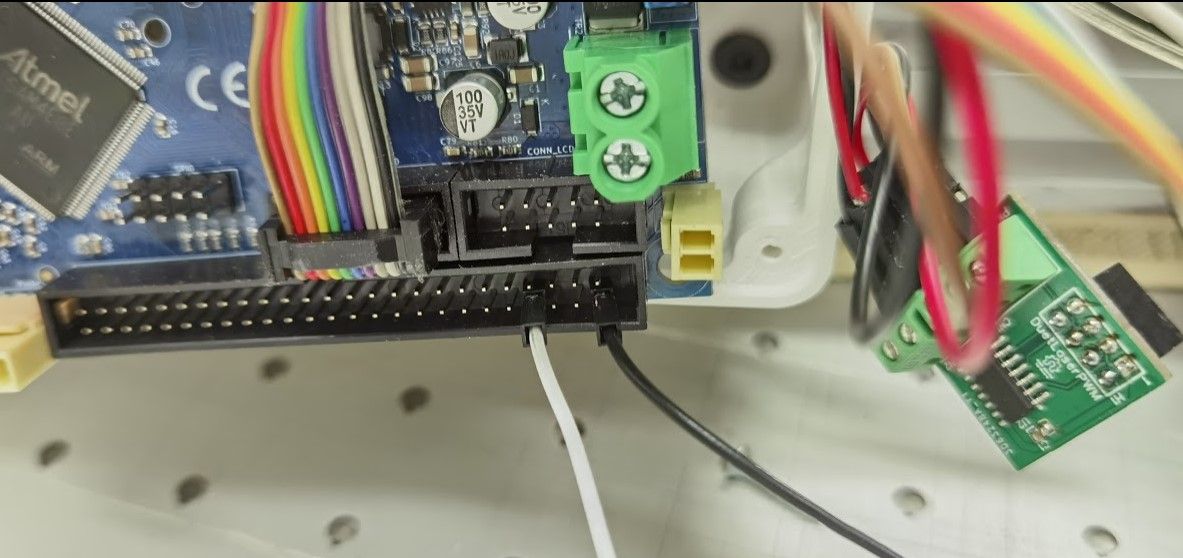
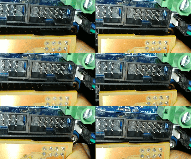
@g0rg Can you double check that you attached the small board to the correct pins?
I had the same case were the laser was always on until I noticed that the pin-socket that goes into duets expansion header was attached with a offset by one pin... -
@pauledd From my understanding:
if i remove the small board, is it normal to measure 3.7v between gnd and pin8 ?That's actually what i have , with or without the board pinned in place.

-
@pauledd said in Weird Laser Mode:
So then PWM value 2 is the lowest possible setting for my laser... I think I can live with that.
If you are using 255 as the maximum then the lowest is about 1.001. If you use 1.0 as the maximum then you can go as low as you like, within the limits of the resolution of the PWM generator.
-
@g0rg said in Weird Laser Mode:
if i remove the small board, is it normal to measure 3.7v between gnd and pin8 ?
Well, I would expect 3.3V, I dont know why you read 3.7V ?
Yes on the bare pin I would expect High level right after boot, and the attached board should invert the logic to 0V until you issue your laser commands.Thats the problem I had:

-
@g0rg said in Weird Laser Mode:
if i remove the small board, is it normal to measure 3.7v between gnd and pin8 ?
It should be 3.3V.
-
@pauledd You got it ! Same idiot issue. I put the board on the right pins and it works now.
Sometimes more than 2 eyes and a good reactive forum helps.
Thank you very much guys ! -
So @pauledd how do you focus your laser now?
I need to do some engravings today and I haven‘t used the laser since I updated the RRF to 3.3, so I fear I will have some troubles there.
I understand the safety issue behind, but I used to use the laser at 1% power to align it with my work and also focus. I don‘t understand how I am supposed to do it now if the laser can only be ON while moving…

