Sure:
http://p-bg.de/files/AnyDuet_config.rar
But be careful and always have one finger in the power switch when testing my config. Config without warranty 
Sure:
http://p-bg.de/files/AnyDuet_config.rar
But be careful and always have one finger in the power switch when testing my config. Config without warranty 
Hi
I just want to show you what can be done with a laser module and the Duet Wifi Board.
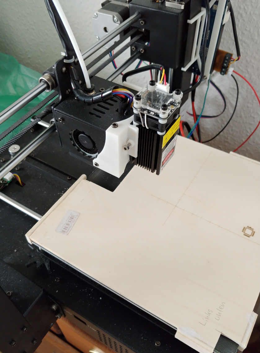
Last year I modified my Anycubic I3 Mega and ripped out its propietary brain and put a Duet Wifi in. It printed very well so my next desire was to attach a uv-laser module to it and improve my pcb exposing process and leave off the old toner transfer method.
I ordered an cheap 30€ 400nm 0.5Watt UV-Laser module and I was able to expose my photosensitive pcb's with a pwm power of 5 (of 255) and a speed of 300mm/s. This is quite slow but if I go faster I encounter a lot of jitter on small traces. So I currently can etch traces as small as 10mil (0,25mm). I did not try to go lower but I think this is still possible. Maybe its quite impractical to attach the laser to the printhead-front. That might introduce quite some mass to the construction while the head is lasering and doing rapid moves.

But the best is, the laser workflow is much less stressful and more consistent in good results.
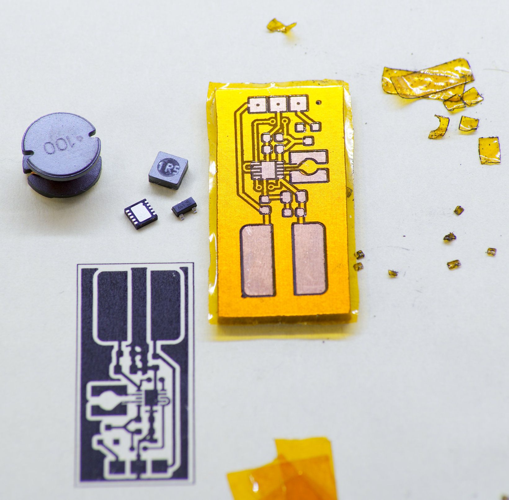
I even just tried to create a solder mask by cutting simple kapton tape, and to my surprise this worked too, with a laser power of 150 and speed 300mm/s, but with two passes.
On this board (1,6x3,3cm) the big traces are 12mil. The little IC is a 3x3mm LFCSP with 0,5mm pads pitch. I have no clue if I can solder that tiny thing 

So I am very pleased with the results that the Duet-Laser already delivers with even more room for optimization 

PS. I use Kicad-->Flatcam to prepare my gcode files but I had to write a python script to further postprocess the gcode file from flatcam, because flatcam was made for CNC, not for laser. So I had to exchange the drill commands in the gcode with laser-on/off commands...
@EasyTarget said in Turn laser only on?:
What happens if you do the same with M3?
Works! 
Can now turn ON/OFF the Laser with M3 S255, M3 S0
Thanks.
@grizewald thanks 
Works now!
What I did:
config.g:
homeall.g:
homez.g:
G91               ; relative positioning

G1 Z10 F3000 H2   ; lift Z relative 10mm

; split Z motor control to Z and U
; for it to work we have to show U (param P4) in the UI
M584 Z2:3 U3 P4

; Move Z and U  down until the switches triggers
G1 Z-205 U-205 F100 H1

; back to combined axes and hidden U
M584 Z2:3 U3 P3

; Back to absolute positioning
G90

; Tell the firmware where we are
G92 Z0

; lift Z after probing
G91
G1 Z10 F1000
G90
Tomorrow I have the fans on my list 
@g0rg said in Weird Laser Mode:
if i remove the small board, is it normal to measure 3.7v between gnd and pin8 ?
Well, I would expect 3.3V, I dont know why you read 3.7V ?
Yes on the bare pin I would expect High level right after boot, and the attached board should invert the logic to 0V until you issue your laser commands.
Thats the problem I had:

@grizewald
Thanks a lot! I changed the lines to your suggestions.
If I now HOME-Z and I trigger the left endstop the right stepper stops moving and the left stepper keeps moving until I trigger the right endstop.
And vice versa if I trigger the the right endstop first the left stepper stops moving and the right stepper keeps moving until I trigger the left endstop.

So the behaviour is now much more kind of correct but exactly the opposite of what I expected, that is to say left endstop stops left stepper, right endstop stops right stepper. I double checked that I didnt twist the endstops accidentally but they are in the correct socket as drawn in the image above.
Shall I twist them simply to make them behave correctly or is there still somewhere a misconfiguration perceivable
@g0rg Can you double check that you attached the small board to the correct pins?
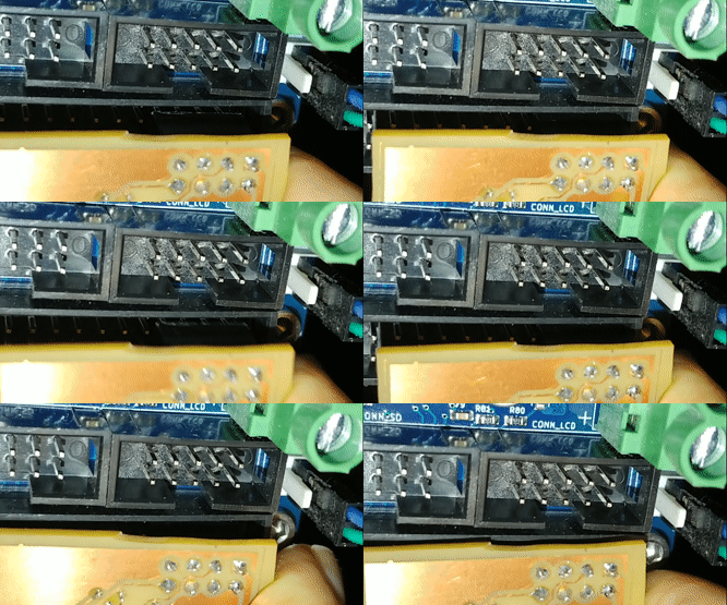
I had the same case were the laser was always on until I noticed that the pin-socket that goes into duets expansion header was attached with a offset by one pin...
Seems to work, will test extensively tomorrow but I am quite optimistic, thanks so far 
Thanks, I again missed that, so I will mark S1 & S0 as NOT PWM in my brain. 
I was irritated because I worked with the M3 S1 command over a year and that did not set the laser to FULL power, insead it used 1/255th PWM...
So then PWM value 2 is the lowest possible setting for my laser... I think I can live with that.
I did a lot of "Homings" today and the Z-axis didn't crash in the endstops again. I consider this Anycubic to Anyduet conversion as success! 
The rest is just optimizing, putting all the stuff together an waiting for delivery of new cables. Thanks a lot for your help.
@Phaedrux said in Error: Pin 'exp.heater3' is not free (SOLVED):
Should probably update to the full 3.2.2 release.
Yes, but I am currently in a project where I heavily rely on my duets functionality. The nightmare update from FW V 2. to 3.x deters me from doing another update right now. 

Board: Duet 2 WiFi (2WiFi)
Firmware: RepRapFirmware for Duet 2 WiFi/Ethernet 3.2-beta3.2 (2020-11-12)
Duet WiFi Server Version: 1.23
config.g:
M584 X0 Y1 Z2:3 U3 E4 P3

G90                                                     ; send absolute coordinates...
M83                                                     ; ...but relative extruder moves
M550 P"PaulsPrinter"                                    ; set printer name

; Network
M552 S1                                                 ; enable network
M586 P0 S1                                              ; enable HTTP
M586 P1 S0                                              ; disable FTP
M586 P2 S0                                              ; disable Telnet

; Drives
M569 P0 S0                                              ; physical drive 0 goes back
M569 P1 S0                                              ; physical drive 1 goes back
M569 P2 S1                                              ; physical drive 2 goes forwards
M569 P3 S1                                              ; physical drive 3 goes forwards
M569 P4 S1                                              ; physical drive 3 goes forwards

M350 X16 Y16 Z16 U16 E16 I1                                 ; configure microstepping with interpolation
M92 X80.02 Y80.07 Z398.00 U398.00 E92.60                       ; set steps per mm
M566 X900.00 Y900.00 Z12.00 U12.00 E12.00                      ; set maximum instantaneous speed changes (mm/min)
M203 X4000 Y4000 Z360.00 U360.00 E1200                  ; set maximum speeds (mm/min)
M201 X2000.00 Y2000.00 Z50.00 U50.00 E250.00                    ; set accelerations (mm/s^2)
M906 X1200 Y1200 Z1200 U1200 E1200 I30                        ; set motor currents (mA) and motor idle factor in per cent

M84 S10                                                 ; Set idle timeout

; Axis Limits
M208 X-115 Y-107.5 Z0 U0 S1                                ; set axis minima
M208 X107.5 Y107.5 Z205 U205 S0                              ; set axis maxima

; Endstops
M574 X1 S1 P"!xstop"                                     ; configure active-high endstop for low end on X via pin xstop
M574 Y1 S1 P"!ystop"                                     ; configure active-high endstop for low end on Y via pin ystop
M574 Z1 S1 P"!zstop"                                     ; configure active-high endstop for low end on Z via pin zstop
M574 Z1 S1 P"!e0stop"

; Z-Probe
M558 P0 H40 F120 T3000                                   ; disable Z probe but set dive height, probe speed and travel speed
M557 X-107:107 Y-107:107 S20                            ; define mesh grid

; Heaters

M308 S0 P"bedtemp" Y"thermistor" T100000 B4725 C7.06e-8 ; configure sensor 0 as thermistor on pin bedtemp
M950 H0 C"bedheat" T0                                   ; create bed heater output on bedheat and map it to sensor 0
M307 H0 R0.430 C483.3 D1.01 S1.00 V12.3 B0
M140 H0                                                 ; map heated bed to heater 0
M143 H0 S90                                             ; set temperature limit for heater 0 to 90C
M308 S1 P"e0temp" Y"thermistor" T100000 B4725 C7.06e-8  ; configure sensor 1 as thermistor on pin e0temp
M950 H1 C"e0heat" T1                                    ; create nozzle heater output on e0heat and map it to sensor 1
M307 H1 R2.838 C175.3 D10.39 S1.00 V12.5 B0				; PID tuning

; Fans
M950 F0 C"fan0" Q500                                    ; create fan 0 on pin fan0 and set its frequency
M106 P0 S0 H-1                                          ; set fan 0 value. Thermostatic control is turned off
M950 F1 C"fan1" Q500                                    ; create fan 1 on pin fan1 and set its frequency
M106 P1 S1 H1 T45                                       ; set fan 1 value. Thermostatic control is turned on

; Tools
M563 P0 D0 H1 F0                                        ; define tool 0
G10 P0 X0 Y0 Z0                                         ; set tool 0 axis offsets
G10 P0 R0 S0                                            ; set initial tool 0 active and standby temperatures to 0C

; Custom settings are not defined

; Miscellaneous
M575 P1 S1 B57600                                       ; enable support for PanelDue
Hi there
When I do things in laser mode I activate it by this command:
M452 C"!exp.heater3" R255 S1 F2000 ;
and when I'm finished I go back to normal mode with this command:
M451
But then I want to reconfigure my exp.heater3 pin to P0:
M950 P0 C"!exp.heater3" Q1000
But that gets denied with this error message:
Error: Pin 'exp.heater3' is not free
What is the correct way to free exp.heater3 after having it used in laser mode?
@g0rg said in Weird Laser Mode:
if i remove the small board, is it normal to measure 3.7v between gnd and pin8 ?
Well, I would expect 3.3V, I dont know why you read 3.7V ?
Yes on the bare pin I would expect High level right after boot, and the attached board should invert the logic to 0V until you issue your laser commands.
Thats the problem I had:

@g0rg Can you double check that you attached the small board to the correct pins?
I had the same case were the laser was always on until I noticed that the pin-socket that goes into duets expansion header was attached with a offset by one pin...
Thanks, I again missed that, so I will mark S1 & S0 as NOT PWM in my brain. 
I was irritated because I worked with the M3 S1 command over a year and that did not set the laser to FULL power, insead it used 1/255th PWM...
So then PWM value 2 is the lowest possible setting for my laser... I think I can live with that.
@Phaedrux said in Weird Laser Mode:
I'm not sure if it would matter either but there are other expansion heater pins to try. I don't know if all are created equal.
The problem is, my laser pcb pinout has been designed according to
which involves exp.heater3
I tried exp.heater3 as servo pin and I detached my laser inverter logic just to be sure this is not another error source...
from a fresh booted Duet...
; initial voltage 3.276V on exp.heater3
M950 P0 C"exp.heater3" Q1000 ; voltage now at 0.0005V
M42 P0 S1 ; 3.310V  ??? WTF
M42 P0 S2 ; 0.0274V check!
M42 P0 S3 ; 0.0402V check!
M42 P0 S4 ; 0.0529V check!
M42 P0 S5 ; 0.0658V check!
M42 P0 S128 ; 1.656V check!
M42 P0 S253 ; 3.274V check!
M42 P0 S254 ; 3.287V check!
M42 P0 S255 ; 3.302V check!
So, except M42 P0 S1, which is exactly what I want... everything else seems to work.
The same strange behavior happens if I reverse the logic:
M950 P0 C"!exp.heater3" Q1000 ; voltage now at 3.302V
M42 P0 S1 ; 0.0005V  ??? WTF
M42 P0 S2 ; 3.274V check!
M42 P0 S3 ; 3.262V check!
M42 P0 S4 ; 3.248V  check!
M42 P0 S5 ; 3.240V check!
M42 P0 S128 ; 1.646V check!
M42 P0 S253 ; 0.0267V check!
M42 P0 S254 ; 0.0138V check!
M42 P0 S255 ; 0.0005V check!
@Phaedrux said in Weird Laser Mode:
I wonder if it would behave differently if it was configured as a servo i/o pin and controlled with M42 instead.
That is definitely worth a try, I'll test that tomorrow, thanks.