@resam Sorry for the late reply! I am no longer using RRF, so I can't test your update. Thank you for keeping me in mind, though!
Posts made by tfjield
-
RE: Cura gcode Save to Disk with Thumbnailsposted in General Discussion
-
RE: Intermittent WiFi Connection at Startupposted in General Discussion
@Exerqtor LOL, yeah, I know...
 I really like RRF! This was my first time using it, and not only is it great, but the support here is top notch. Kudos to @Phaedrux and @dc42 and everyone else that contributes.
I ended up changing because I have a rather large printer (600 x 600 x 600 mm) that I'm using to print large prototypes of something before we invest in injection molding, and I need to crank them out as fast as possible. I upgraded my hotends to Takotos (they're great!) and went to Klipper, both for the speed. At this point, I think I'm limited by the residual stress in the plastic that causes warping if I try to print any faster.
Good luck with your problem! I'm with you, it didn't seem like hardware to me because it never dropped the connection once it got it. It was only during startup. And if I remember right, I could get it to connect again by turning the module off and on via software, but my memory here is hazy at this point... Clearing out those other SSID's made sense to me that it could have been the problem, but I really didn't run it long enough afterwards to confirm. I rarely restart my machine, so the annoyance wasn't a daily thing and it took quite a while to get any useful stats.
-
RE: Intermittent WiFi Connection at Startupposted in General Discussion
@Exerqtor Hey! I ended up switching to Klipper soon after my last post on this issue, so I don't use the WiFi on the Duet anymore.
But before I switched, one of the last things I did was check the WiFi networks that had been associated with my card using M587, and I found that there were a couple that were not on my network, not added by me; perhaps they were there from testing of the board or something, or maybe just corrupt memory? Anyway, I removed them all using M588 (I had to use M588 S"*" because one of the network names had weird, unprintable characters in it).
Then I re-associated with my network and confirmed that was the only one listed via M587.I can't say that solved the problem, but for the last several reboots before I upgraded it was connecting OK. Do you happen to have any spurious networks listed when you issue M587?
-
RE: Mesh Bed Compensation Capabilitiesposted in General Discussion
I ended up getting my problems all sorted out. But I had to do several things:
- Increase the supports for my bed so that it was closer to level to start with. My bed is a bit over 600 mm x 600 mm and wasn't sufficiently supported, so there was a significant sag in the middle. Now I still have some sag, but my maximum variance across the surface is 0.387 mm.
- Fix the twist in my gantry. There was a couple degree twist along my y-axis, and due to the location of my BL Touch relative to my nozzle, just a degree resulted in a very significant height error. One degree of twist was over 0.4 mm of height error.
- I picked a common point on one corner for my z-axis datum, my probe z offset, my bed tilt probing points, and my bed mesh compensation.
- Performed a high resolution map (21 x 21) at temperature.
- Modified my macros so that for every print it will do the following:
o Verify that the axes have been homed. If not, home them.
o Verify that the bed has been adjusted for tilt. If not, adjust it, and home z again.
o Turn on bed mesh compensation.
I do not like the commonly accepted approach of using the center of the bed for my z datum. I work in a field where I'm very conscious of how things fail, and I don't want my datum at what is most likely the lowest point on my bed. If, for some reason, I don't turn on bed mesh compensation and I'm zeroed at that point, them I'm likely to run into my bed as I move away from the center and screw up my print head and PEI sheet. So I want my datum at one of the highest points.
Also, I want the corners of my bed tilt and bed mesh to be identical to my datum point, and use the same exact point for measuring the probe's z offset. In this way, it's easy for me to verify that everything is working right. My bed mesh should show zero compensation at that corner, and because I've already corrected the tilt, all four corners of the bed mesh should show almost zero compensation.
It's been a few weeks and several km of filament since I last took a bed mesh map, and my prints are rock-solid every time, now.
-
RE: New Input Shaping plugin v3.4.1-b1posted in Plugins for DWC and DSF
@oliof As I had posted in another thread, I measured my frequencies and applied a shaper and measured again and it looked good. (I haven't posted my results, yet.) But when I printed a test part, the ringing was noticeably worse.
What would this be an indication of? Damping factor too high?
-
RE: Intermittent WiFi Connection at Startupposted in General Discussion
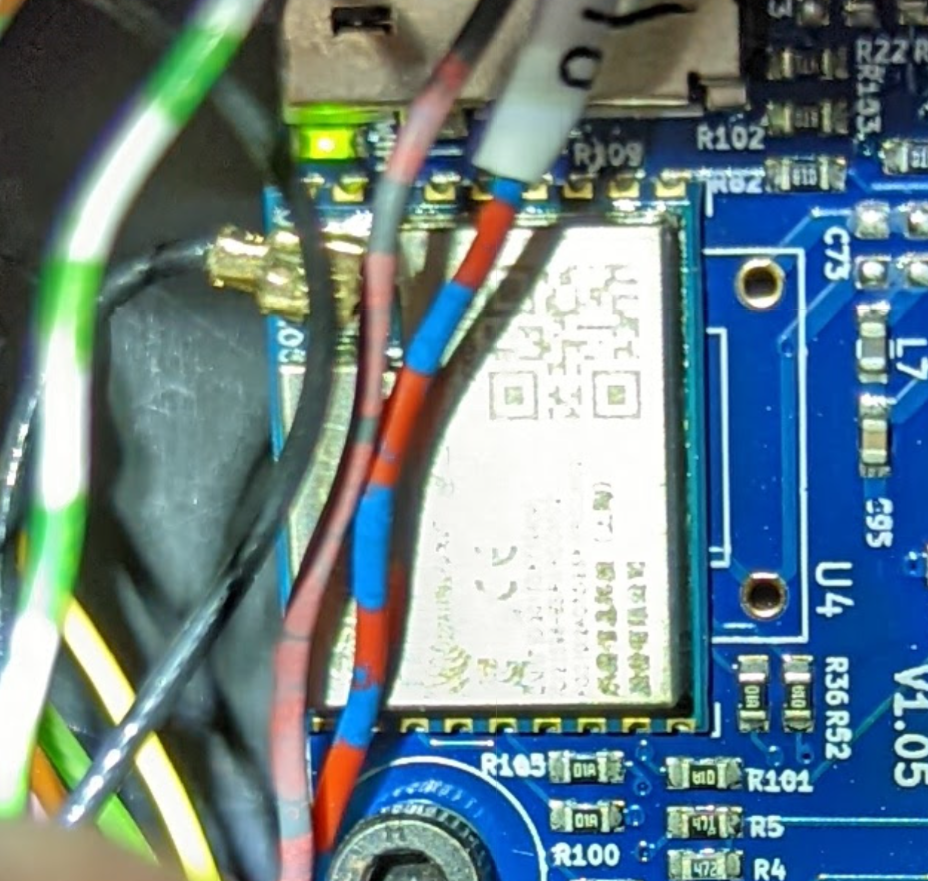
@phaedrux Here are some better pictures. I tried to image near the pads on the bottom.
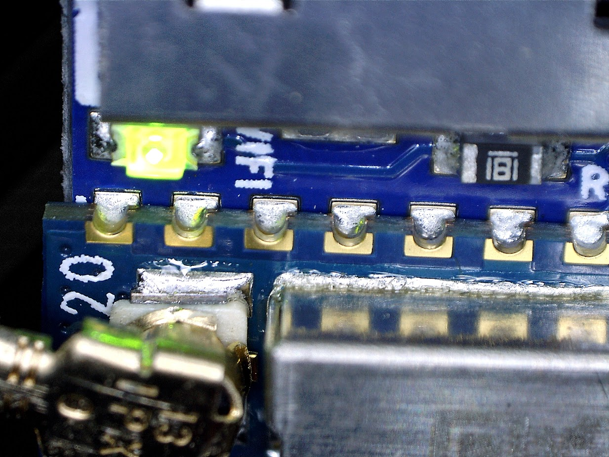
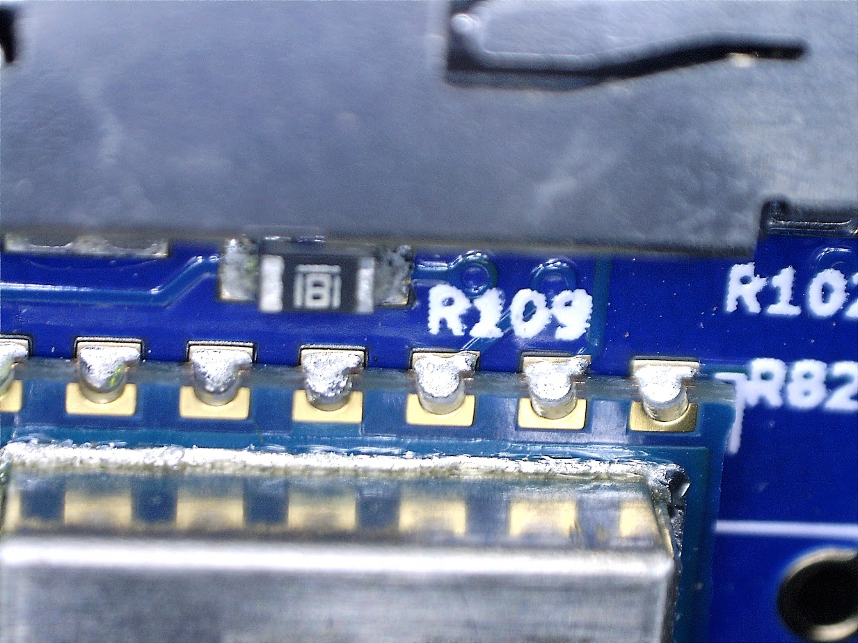
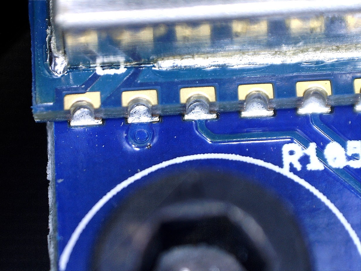
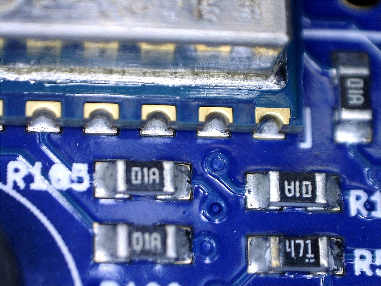
That's about the best I can do.
-
RE: Intermittent WiFi Connection at Startupposted in General Discussion
@phaedrux Sure, I can get better photos. Anything in particular I should try to capture? Are you looking for a cold solder joint? Perhaps it would be better if I viewed it from a 45° angle...
-
RE: Intermittent WiFi Connection at Startupposted in General Discussion
@phaedrux
These aren't great... Is there something specific you're looking for? If so, I can try to highlight it better. And these were with a cell phone camera... If these aren't good enough, I can pull out the USB microscope.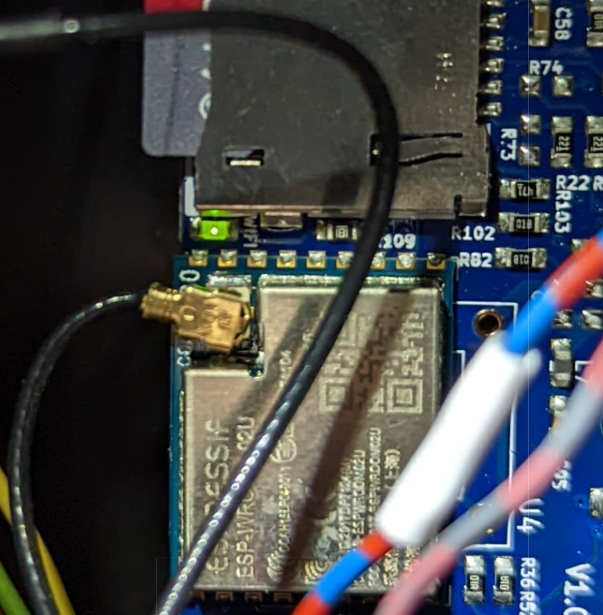
-
RE: Intermittent WiFi Connection at Startupposted in General Discussion
Well, it turns out that this was not the fix. As time went on, the number of times it would fail vs. the number of times that it would succeed has increased a lot. We're back to 50/50 or greater failure rate.
To this day, once the WiFi is connected I have never lost connection.
I suppose this could be a hardware problem, but it sure seems more like some kind of race condition. Is there anything I can do to help determine the root cause for the failure?
-
RE: Using Input Shaping. Any suggestions or advice??posted in General Discussion
@chickenwoman said in Using Input Shaping. Any suggestions or advice??:
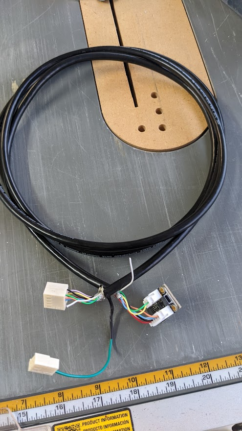
@tfjield this is off topic but what wire did you use on your Modix and what length? I have a Big 60 and have tried several different types of wire and cant get it to work.
The first time I tried I used an old, unshielded network cable and it wouldn't recognize the accelerometer. Then I went with a USB cable.
I followed this guide:
https://forum.duet3d.com/topic/22878/software-package-3-3beta3-released/68?_=1624809172098I purchased this USB cable from Amazon:
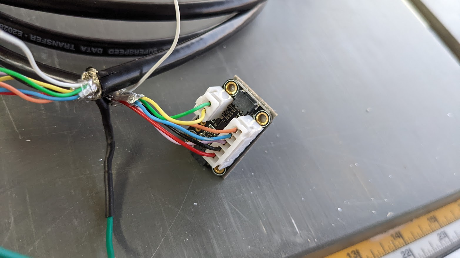
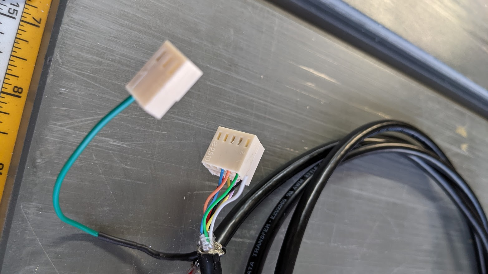
https://smile.amazon.com/dp/B014RWATK2I left the cable at about 5 feet / 1.5 meters. There are two shields inside wrapped around two different pairs, and a shield around the whole thing. I attached all three shields together, and connected it to one of the ground points on the Duet boards. (I have the DueX5, so I used one of the grounds on one of the 5 endstop connectors.)
I use a PT100 daughterboard, and the daughterboard moves CS3 and CS4 from pins 7 and 9 to pins 3 and 1, respectively. So my CS connects to pin 1 and INT connects to pin 3.
EDIT: Here are some pics of my connection. I didn't have a dual inline plug that took crimp connections for the Duet side so I made one with the connectors that I had.
-
RE: Using Input Shaping. Any suggestions or advice??posted in General Discussion
@oliof Thank you! Great idea about the wires; I didn't think of that. I'll add some strain relief to minimize any artifact they might be introducing.
I don't think the x and y being different on this machine means much. In my first photos you can see 4 silver screw heads. Those are the only attachments to the y-axis rail, so that whole head can twist around the y-axis forward and backwards (so the hot end oscillates in the x-direction). There's a bit less play rotating around the x-axis.
But the belts could be contributing. There is one y-axis belt and two x-axis belts, and I know the y tension is higher than the two x's.
-
Using Input Shaping. Any suggestions or advice??posted in General Discussion
I'm starting to look at input shaping (for the first time!), and I could use some guidance...
I've attached the accelerometer (LIS3DH from adafruit) to the Duet2 WiFi, and it appears to be working properly. I configured it with
M955 P0 C"spi.cs4+spi.cs3" I01and I mounted it to my hot end with a zip tie (and some tape to avoid shorting the back).

I'm able to collect data using the Input Shaping Plugin, v4.3.1-b1:
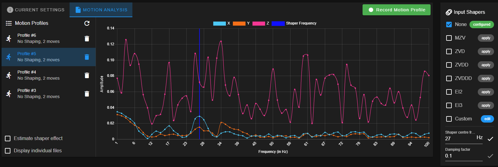
This is with XY maximum speeds set to 16000 mm/min and acceleration set to 3000 mm/sec^2.
This is on a Modix Big-60, and the accelerometer is connected to the printhead, so there is no z-motion. But the big printhead bracket has a decent amount of movement around the y-axis, so I would expect to see some significant ringing along x, and I see see one peak around 27 Hz.
Do these curves look right? (Why all the z-axis data? Is this just a byproduct of the FFT without any strong frequency components?)
Turning on ZVDD at a 27 Hz center frequency (arbitrary choice, and the white checkmark next to the center frequency entry is fun!) gets me this:
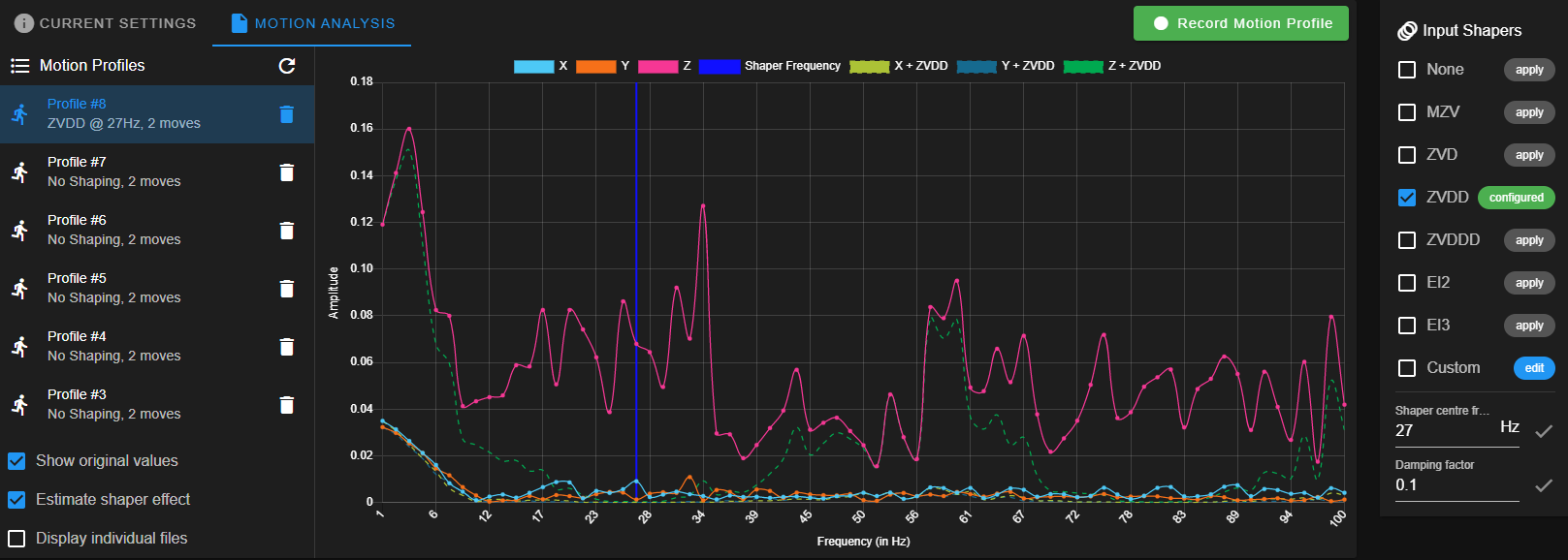
So it seems like it's working, right? Any advise or suggestions? I haven't tried printing any ringing tests, yet.
-
RE: Incorrect extrusion amount on slow and/or small axis movesposted in General Discussion
@fcwilt Oh, you're right, I was thinking backwards. I forgot that he wants to limit extrusion to below the max, not retraction.
-
RE: Incorrect extrusion amount on slow and/or small axis movesposted in General Discussion
@fcwilt Or he could use firmware retraction.
-
RE: Incorrect extrusion amount on slow and/or small axis movesposted in General Discussion
@ardenpm The way I read it, it always applies, but it's especially important for CNC mode. But that's just my interpretation. I'll run a test when I get a chance.
-
RE: Tool Fan and Primary Blower Fan Linked?posted in General Discussion
@jay_s_uk Ah, thank you! That makes sense now that I think about it... I never named the hotend fan "Tool Fan." It just seemed like the tool fan! lol
And thanks @fcwilt!
-
RE: Tool Fan and Primary Blower Fan Linked?posted in General Discussion
@fcwilt I'm sorry, I'm not sure I understand. Are you saying that the "tool fan" isn't actually the fan blowing at my heat break, but it's just another name for the primary blower fan?
-
Tool Fan and Primary Blower Fan Linked?posted in General Discussion
So with Cura I start my first layer with no blower fan, and then increase the fan to 100% at 20 mm. It increases gradually. Today I noticed that DWC is showing that my tool fan is doing the same:
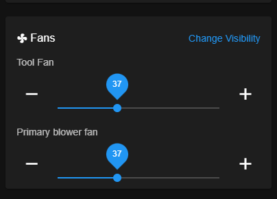
If I try to change one ,the other changes, too.
Here's the relevant section of my config.g:
; Fans______________________________________________________________
M950 F0 C"fan0" Q500                            ; create fan 0 on pin fan0 and set its frequency
M106 P0 S0 H-1 C"Primary blower fan"		; set fan 0 value. Thermostatic control is turned on
M950 F1 C"fan1" Q500                            ; create fan 1 on pin fan1 and set its frequency
M106 P1 S0 H-1 C"Secondary blower fan"		; set fan 1 value. Thermostatic control is turned on
M950 F2 C"duex.fan7" Q500                   	; create LED on pin fan2 and set its frequency
M106 P2 S0 H-1 C"LED"                		; Disable fan channel for LED
M106 P2 S255					; LED on by default
M950 F3 C"duex.fan5" Q500     			; create fan 3 on pin fan1 and set its frequency
M106 P3 S255 H0 T45              		; set fan 3 value. Thermostatic control is turned on
M950 F4 C"duex.fan6" Q500     			; create fan 4 on pin fan1 and set its frequency
M106 P4 S255 H1 T45              		; set fan 4 value. Thermostatic control is turned on
Fan 3 is my tool head fan, and it's thermostatically controlled.
In the files I'm printing, the blower fan speed is increased like this:
M106 S13.4with slowly increasing values.
Any idea what's going on?
-
RE: Incorrect extrusion amount on slow and/or small axis movesposted in General Discussion
@deckingman Yes, that all makes sense, and that's how I would expect it to operate. I'm just trying to figure out why the OP isn't getting the full 50 mm of filament on his
G1 B42 E50 F480move. Unless he's just grinding filament...@ardenpm Can you confirm that
G1 E50 F3600gives you the full 50 mm of filament? -
RE: Incorrect extrusion amount on slow and/or small axis movesposted in General Discussion
@deckingman I'm following this thread with interest!
Everything you said makes sense to me. You said that because his extrusion rate is capped the entire move will slow down. Silly question, but do we know that that is actually what happens? Is it possible that the move just extrudes less material because it extrudes at 3,600 mm/min for 0.25 sec? But if that were the case, even at a feedrate of 250 mm/min it would still only extrude 28.8 mm of filament...
