Using Input Shaping. Any suggestions or advice??
-
I'm starting to look at input shaping (for the first time!), and I could use some guidance...
I've attached the accelerometer (LIS3DH from adafruit) to the Duet2 WiFi, and it appears to be working properly. I configured it with
M955 P0 C"spi.cs4+spi.cs3" I01and I mounted it to my hot end with a zip tie (and some tape to avoid shorting the back).

I'm able to collect data using the Input Shaping Plugin, v4.3.1-b1:
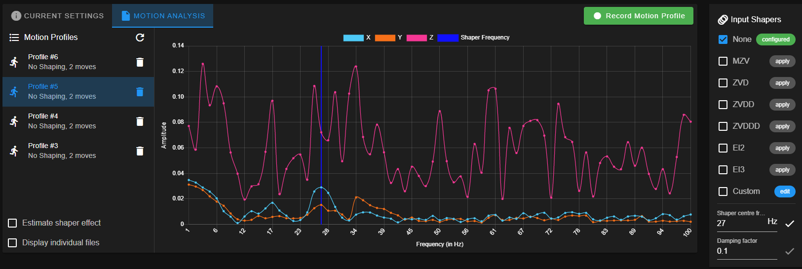
This is with XY maximum speeds set to 16000 mm/min and acceleration set to 3000 mm/sec^2.
This is on a Modix Big-60, and the accelerometer is connected to the printhead, so there is no z-motion. But the big printhead bracket has a decent amount of movement around the y-axis, so I would expect to see some significant ringing along x, and I see see one peak around 27 Hz.
Do these curves look right? (Why all the z-axis data? Is this just a byproduct of the FFT without any strong frequency components?)
Turning on ZVDD at a 27 Hz center frequency (arbitrary choice, and the white checkmark next to the center frequency entry is fun!) gets me this:
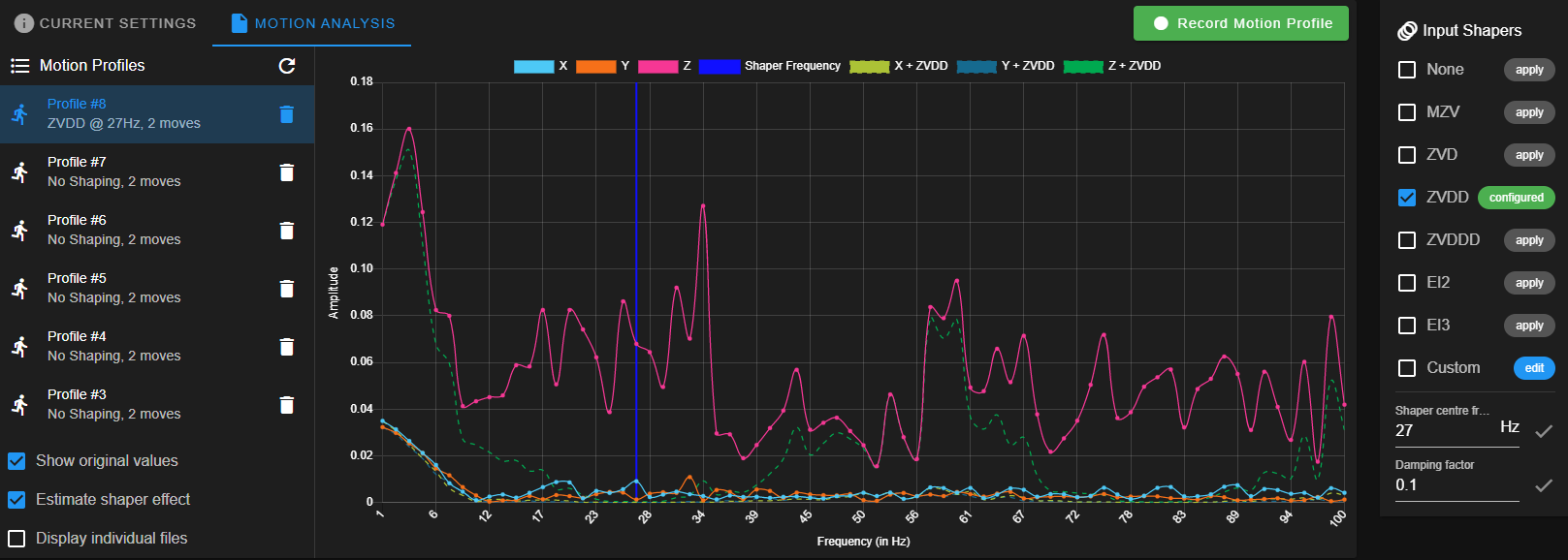
So it seems like it's working, right? Any advise or suggestions? I haven't tried printing any ringing tests, yet.
-
I'd try to add strain relief to the wires as close to the board as possible. Also make sure that you've configured the right orientation of the sensor.
On a CoreXY system, divergent graphs for X and Y are an indicator that the belts aren't equally tensioned. You could try loosening Y tension or increasing X tension a bit to see if it helps.
-
oh also, use two zip ties to fasten the board, one is effectively a lever.
-
@oliof Thank you! Great idea about the wires; I didn't think of that. I'll add some strain relief to minimize any artifact they might be introducing.
I don't think the x and y being different on this machine means much. In my first photos you can see 4 silver screw heads. Those are the only attachments to the y-axis rail, so that whole head can twist around the y-axis forward and backwards (so the hot end oscillates in the x-direction). There's a bit less play rotating around the x-axis.
But the belts could be contributing. There is one y-axis belt and two x-axis belts, and I know the y tension is higher than the two x's.
-
Some variance in the vibration peaks don't matter much due to the damping factor of the IS algorithms. You should measure your second head too to make sure that two X belts have about the same tension as well.
-
@tfjield this is off topic but what wire did you use on your Modix and what length? I have a Big 60 and have tried several different types of wire and cant get it to work.
-
@chickenwoman said in Using Input Shaping. Any suggestions or advice??:
@tfjield this is off topic but what wire did you use on your Modix and what length? I have a Big 60 and have tried several different types of wire and cant get it to work.
The first time I tried I used an old, unshielded network cable and it wouldn't recognize the accelerometer. Then I went with a USB cable.
I followed this guide:
https://forum.duet3d.com/topic/22878/software-package-3-3beta3-released/68?_=1624809172098I purchased this USB cable from Amazon:
https://smile.amazon.com/dp/B014RWATK2I left the cable at about 5 feet / 1.5 meters. There are two shields inside wrapped around two different pairs, and a shield around the whole thing. I attached all three shields together, and connected it to one of the ground points on the Duet boards. (I have the DueX5, so I used one of the grounds on one of the 5 endstop connectors.)
I use a PT100 daughterboard, and the daughterboard moves CS3 and CS4 from pins 7 and 9 to pins 3 and 1, respectively. So my CS connects to pin 1 and INT connects to pin 3.
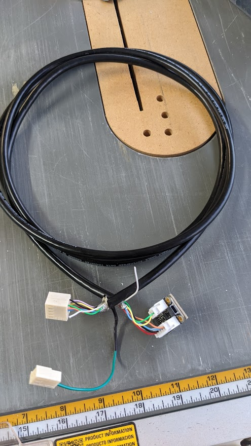
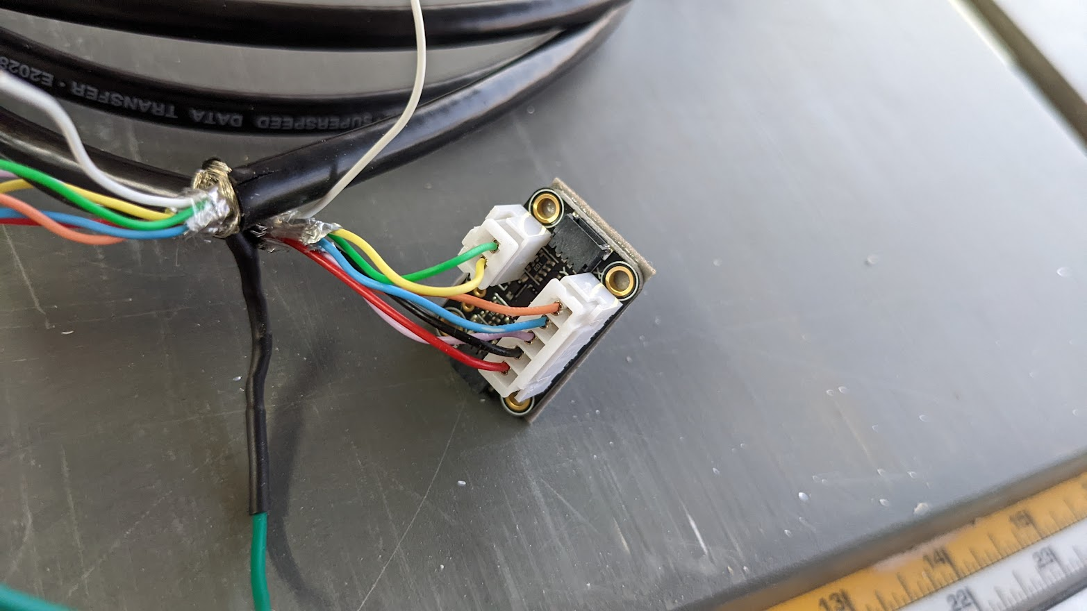
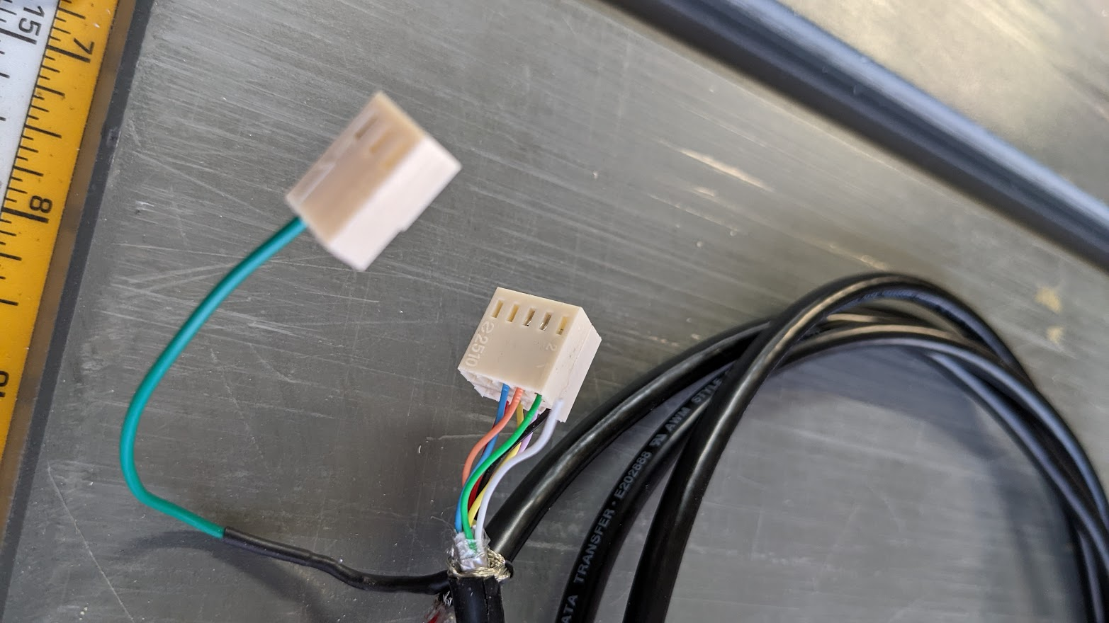
EDIT: Here are some pics of my connection. I didn't have a dual inline plug that took crimp connections for the Duet side so I made one with the connectors that I had.
