@o_lampe Thank You, I try it.
Posts made by Pertti
-
duet2wifi servo control by cellphoneposted in General Discussion
Hi !
I have an extra duet2 wifi which has lost some extruder drivers. My goal is to use it for experiments.Now I managed to connect a servo as advised in the manual wiht external 5v power.
;configuration:
M950 S0 C"exp.heater3" ; assign GPIO port 0 to heater3 on expansion connector, servo mode
;move servo with
M280 P0 S80 ; set 80deg servo position on GPIO port 0
;turn off servo with
M42 P0 S0I made two macros that move the servo.
The problem is that I can not see the macro buttons in my cellphone. I have to go down to the files \ macros to move the servo.
Is it possible to use the fan control slider and how? -
RE: E3D Rapidcahange Revo jamposted in General Discussion
@elmoret Done.
Meanwhile I made a quick repair by recycling used heatblock and thermistor. I also sealed the tube parts with silver soldier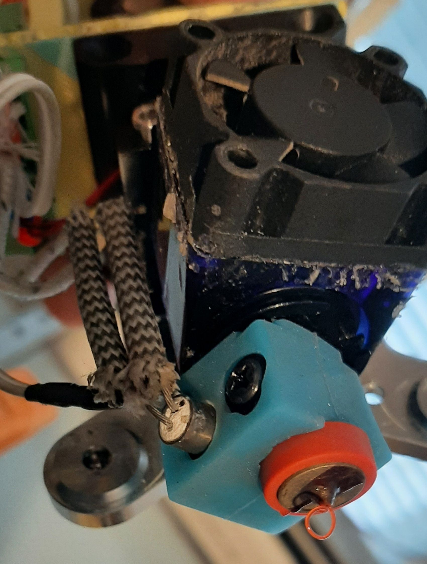
-
E3D Rapidcahange Revo jamposted in General Discussion
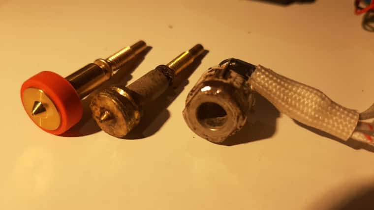
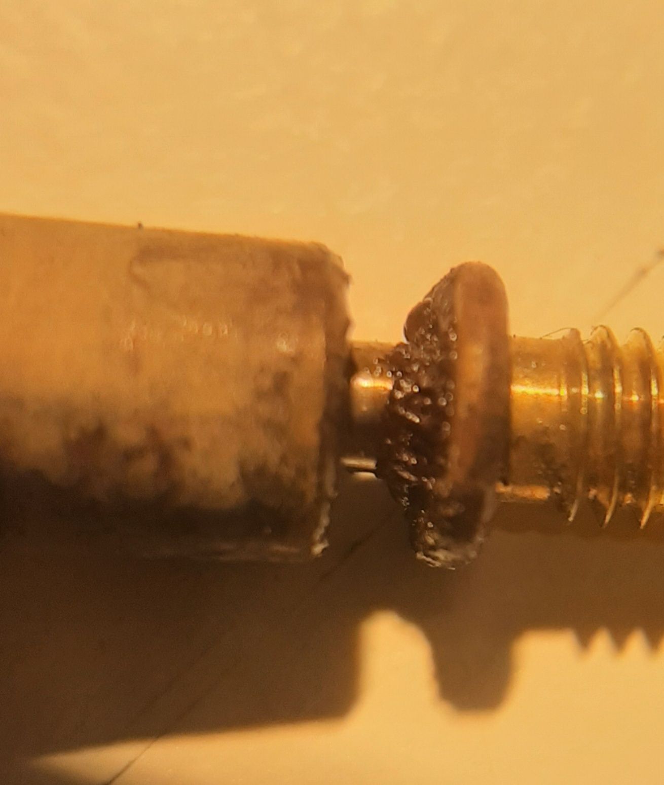
Hi! Sorry to say, but I found it hard to pull out this nozzle of the heatblock. By warming it up by torch it was possible to remove it. Usually You can pull it out with no effort but now I discovered some dark material (propably filament) around the neck of the nozzle. Propably it acts as an insulation, because printing was impossible due blockage.
Perhaps the nozzle leaked from the joint. Left in the picture is a not used nozzle.
-
RE: Why not brushless motors in direct drive extruders?posted in General Discussion
@o_lampe I like this group because of this habit of sharing and commenting innovations.
-
RE: Why not brushless motors in direct drive extruders?posted in General Discussion
Ha-haa, here it is,found in Hollow shaft extruder thread:
https://www.youtube.com/watch?v=f0SuaIMxAs0 -
3d printed nozzles?posted in General Discussion
Just wondering if there are metal 3d printted nozzles. The method would allow interesting shapes in order to produce fast filament flow.
-
RE: Revo Six Heater 5 fault and temperature readingsposted in Duet Hardware and wiring
@Phaedrux Ok, looks like a thermistor issue.
-
Revo Six Heater 5 fault and temperature readingsposted in Duet Hardware and wiring
My Revo Six has some difficulties in reaching temperatures over 200 degreeds.
Error: Heater 5 fault: temperature rising too slowly: expected 1.70°C/sec measured 0.55°C/sec
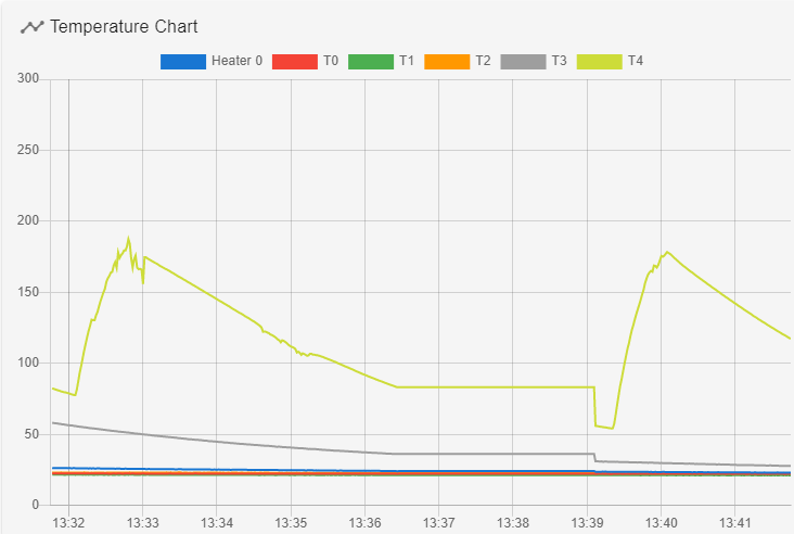
I run M303 H5 S240
result:
M307 H5 R1.801 K0.337:0.000 D1.40 E1.35 S1.00 B0 V24.0
The test looks like this:
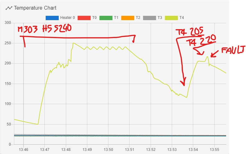
The temperature readings seem to fly through rouhg air...
Do I need a new E3D Revo heatercore perhaps?Board: Duet 2 WiFi (2WiFi)******************
Firmware: RepRapFirmware for Duet 2 WiFi/Ethernet 3.4.1 (2022-06-01) -
How to park the last tool?posted in Gcode meta commands
Hi !
After finishing the job my Toolchanger moves the printhead to the left. Every time I start a new job I have to manually remove the (last) tool from the toolchanger and put it back in the dock.
I put my hope to the meta commands.
Logically there should exist a variable that tells the number of the last tool. Is it [state.currentTool ]? Or should I put a variable [set.lasttool=#] In the macro T# - Pick ?
Then in Cura I can add the end gcode like
[if lasttool=# then T# - Drop] for every tool of course.
Maybe there is a smart solution somewhere i have not seen yet.
And are there tutorials somewhere available?
Thanks in advance.Board: Duet 2 WiFi (2WiFi)
Firmware: RepRapFirmware for Duet 2 WiFi/Ethernet 3.4.1 (2022-06-01) -
RE: PrusaSlicer 2.5.0 , toolchanger problemposted in Third-party software
@dc42 Thanks! I try this:
...add command G1 R2 X0 Y0 Z2 Fxxx followed by G1 R2 Z0 Fxxx to the end of your tpost#.g files...
Looks like it works. Maybe better if the last leg before the new-tool-print-start could travel i mm higher, now it is scratching the print a little. I'm using the rapid change hotends an they can bend easily when touching the print.
Here I want to ask how to set standby temperatures to tools. I did not find such a feature in Prusa.
And how to tell the machine to put back the last tool after finishing the job. -
PrusaSlicer 2.5.0 , toolchanger problemposted in Third-party software
Hi, I made my first attempt to slice with Prusaslicer a multicolor test. Cura works fine but the Prusa rises the nozzle about 10 mm when changing the tool. I do hope to get the Prusa´s nice painting feature in action. Any Idea what is it all about? As far as I can see there is no problem with the G-Code Z values.
Macros perhaps?
Curatest.gcode
Prusatest.gcode
config.g tpre0.g tpre1.g tfree0.g tfree1.gBoard: Duet 2 WiFi (2WiFi)
Firmware: RepRapFirmware for Duet 2 WiFi/Ethernet 3.4.1 (2022-06-01)
Duet WiFi Server Version: 1.26 -
RE: Two parallel part cooling fansposted in Tuning and tweaking
@tecno I have tried, but some work some don´t.
-
Two parallel part cooling fansposted in Tuning and tweaking
I have wired two parallel part cooling fans per tool. Some fans work together, some do not. Is it okay to connect two fans parallel?
-
RE: Assigning multiple cooler fansposted in Tuning and tweaking
@pertti
Now I got the idea, thanks. -
RE: Assigning multiple cooler fansposted in Tuning and tweaking
@droftarts
Thanks, I need to study my g-codes better. -
RE: Assigning multiple cooler fansposted in Tuning and tweaking
I can not see any fans here in the "Heaters" section.
M308 S2 P"e1temp" Y"thermistor" A"T1" T100000 B4725 C7.06e-8 ; Set thermistor
M950 H2 C"e1heat" T2 ; Extruder 1 heater
M143 H2 S300 ; Set temperature limit for heater 2 to 300C
M307 H2 B0 R4.431 C82.3:67.5 D1.58 S1.00 V23.9;M307 H2 B0 R3.322 C131.0:103.7 D10.46 S1.00 V23.9 -
Assigning multiple cooler fansposted in Tuning and tweaking
Hi!
I´m wondering where the cooler fans are assigned to tools. I have a 5 tool toolchanger . Part cooling fans are assigned in the Tools section but can´t find the cooler fans. They work, however.
I have possibly ruined fans from the duet2 wifi board, is it possible to power them from extra heaters I have in duex 5?Board: Duet 2 WiFi (2WiFi)
Firmware: RepRapFirmware for Duet 2 WiFi/Ethernet 3.4.1 (2022-06-01)
Duet WiFi Server Version: 1.26; Configuration file for Duet WiFi / Ethernet running RRF3.01 on E3D Tool Changer com
; executed by the firmware on start-up
; Board#3 220203
; General preferencesM111 S0 ; Debugging off
G21 ; Work in millimetres
G90 ; Send absolute coordinates...
M83 ; ...but relative extruder moves
M555 P2 ; Set firmware compatibility to look like Marlin; Network
M550 P"ToolChanger" ; Set machine name
M552 S1 ; Enable Networking
M586 P0 S1 ; Enable HTTP
M586 P1 S0 ; Disable FTP
M586 P2 S0 ; Disable TelnetM667 S1; M669 K1;M667 S1 ; Select CoreXY mode
;Stepps: 650-700 steps/mm at 16 micro-stepping
;Acceleration: 600 mm/s^2
;Maximum instantaneous speed change (jerk): 300 mm/min(RRF), 5 (Marlin)
;Maximum speed: 3600 mm/min; Drive direction
M569 P0 S0 ; Drive 0 X
M569 P1 S1 ; Drive 1 Y
M569 P2 S1 ; Drive 2 Z
M569 P3 S1 ; Drive 3 E0
M569 P4 S1 ; Drive 4 E1
M569 P5 S0 ; Drive 5 E2
M569 P6 S1 ; Drive 6 E3
M569 P7 S1 ; Drive 7 COUPLER
M569 P8 S1 ; Drive 8 E4
M569 P9 S1 ; Drive 9 UNUSED;Stepps: 650-700 steps/mm at 16 micro-stepping
;Acceleration: 600 mm/s^2
;Maximum instantaneous speed change (jerk): 300 mm/min(RRF), 5 (Marlin)
;Maximum speed: 3600 mm/minM584 X0 Y1 Z2 C7 E3:4:5:6:8 ; Apply custom drive mapping
M208 X-163:173.0 Y-150:246.0 Z0:200 C0:500 ; Set axis maxima & minima
M92 X79.94 Y79.94 Z640.20 C200 E650:650:650:650:650 ; Set steps per mm assuming x16 microstepping
M350 E16:16:16:16:16 I1 ; Configure microstepping with interpolation
M350 C16 I1
M350 X16 Y16 Z16 I1 ; Configure microstepping with interpolation
M566 X400 Y400 Z8 C2 E200:200:200:200:200 ; Set maximum instantaneous speed changes (mm/min) was E680
M203 X35000 Y35000 Z180 C10000 E3600:3600:3600:3600:3600 ; Set maximum speeds (mm/min) Z1200->
M201 X5500 Y5500 Z400 C500 E600:2500:2500:2500:2500 ; Set accelerations (mm/s^2)
M906 X1600 Y1600 Z1600 C500 E800:800:800:800:800 I30 ; Set motor currents (mA) and motor idle factor in percent z1600!!!X:Y2000
M913 C50
M84 S120 ; Set idle timeout; Endstops
M574 X1 Y1 S3 ; Set X / Y endstop stall detection
M574 Z0 ; No Z endstop
M574 C1 S3 ; Stall detect coupler at low end of its range; Z probe
M558 P8 C"zstop" H3 F360 I0 T10000 ; Set Z probe type to switch, the axes for which it is used and the dive height + speeds
G31 P200 X0 Y0 Z0 ; Set Z probe trigger value, offset and trigger height
M557 X-140:140 Y-80:160 S40 ; Define mesh grid;Stall Detection
M915 C S6 F0 H200 R4700 ; Coupler;Stall Detection
M915 X Y S3 F0 H400 R4700 ; X / Y Axes; Heaters
M308 S0 P"bedtemp" Y"thermistor" T100000 B4138 ; configure sensor 0 as thermistor on pin bedtemp
M950 H0 C"bedheat" T0 ; create bed heater output on bedheat and map it to sensor 0
M307 H0 B0 R0.078 C877.1 D17.57 S1.00 V23.6
M140 H0 ; map heated bed to heater 0
M143 H0 S120 ; set temperature limit for heater 0 to 120CM308 S1 P"e0temp" Y"thermistor" A"T0" T100000 B4725 C7.06e-8 ; Set thermistor
M950 H1 C"e0heat" T1 ; Extruder 0 heater
M143 H1 S300 ; Set temperature limit for heater 1 to 300CM307 H1 B0 R5.648 C96.6:88.8 D0.84 S1.00 V23.9 ;M307 H1 B0 R1.867 C209.9:171.1 D19.05 S1.00 V23.9
M308 S2 P"e1temp" Y"thermistor" A"T1" T100000 B4725 C7.06e-8 ; Set thermistor
M950 H2 C"e1heat" T2 ; Extruder 1 heater
M143 H2 S300 ; Set temperature limit for heater 2 to 300C
M307 H2 B0 R4.431 C82.3:67.5 D1.58 S1.00 V23.9;M307 H2 B0 R3.322 C131.0:103.7 D10.46 S1.00 V23.9M308 S3 P"e2temp" Y"thermistor" A"T2" T100000 B4725 C7.06e-8 ; Set thermistor
M950 H3 C"duex.e2heat" T3 ; Extruder 2 heater
M143 H3 S300 ; Set temperature limit for heater 3 to 300C
M307 H3 B0 R3.620 C144.7:136.2 D1.37 S1.00 V24.0M308 S4 P"e3temp" Y"thermistor" A"T3" T100000 B4725 C7.06e-8 ; Set thermistor
M950 H4 C"duex.e3heat" T4 ; Extruder 3 heater
M143 H4 S300 ; Set temperature limit for heater 4 to 300C
M307 H4 B0 R4.342 C118.5:109.5 D2.45 S1.00 V24.0M308 S5 P"e4temp" Y"thermistor" A"T4" T100000 B4725 C7.06e-8 ; Set thermistor
M950 H5 C"duex.e4heat" T5 ; Extruder 4 heater
M143 H5 S300 ; Set temperature limit for heater 4 to 300C
M307 H5 B0 R4.342 C118.5:109.5 D2.45 S1.00 V24.0; Tools
M563 P0 S"T0" D0 H1 F2 ; Define tool 0
G10 P0 X0 Y0 Z0 ; Reset tool 0 axis offsets
G10 P0 R0 S0 ; Reset initial tool 0 active and standby temperatures to 0CM563 P1 S"T1" D1 H2 F4 ; Define tool 1
G10 P1 X0 Y0 Z0 ; Reset tool 1 axis offsets
G10 P1 R0 S0 ; Reset initial tool 1 active and standby temperatures to 0CM563 P2 S"T2" D2 H3 F6 ; Define tool 2
G10 P2 X0 Y0 Z0 ; Reset tool 2 axis offsets
G10 P2 R0 S0 ; Reset initial tool 2 active and standby temperatures to 0CM563 P3 S"T3" D3 H4 F8 ; Define tool 3
G10 P3 X0 Y0 Z0 ; Reset tool 3 axis offsets
G10 P3 R0 S0 ; Reset initial tool 3 active and standby temperatures to 0CM563 P4 S"T4" D4 H5 F0 ; Define tool 4
G10 P4 X0 Y0 Z0 ; Reset tool 3 axis offsets
G10 P4 R0 S0 ; Reset initial tool 3 active and standby temperatures to 0C; Fans
; Fan0 output is used
M950 F0 C"fan0"
M950 F1 C"fan1"
M950 F2 C"fan2"
M950 F3 C"duex.fan3"
M950 F4 C"duex.fan4"
M950 F5 C"duex.fan5"
M950 F6 C"duex.fan6"
M950 F7 C"duex.fan7"
M950 F8 C"duex.fan8"M106 P1 S255 H1 T70 ; T0 HE
M106 P2 S0 ; T0 PCF
M106 P3 S255 H2 T70 ; T1 HE
M106 P4 S0 ; T1 PCF
M106 P5 S255 H3 T70 ; T2 HE
M106 P6 S0 ; T2 PCF
M106 P7 S255 H4 T70 ; T3 HE
M106 P8 S0 ; T3 PCF
M106 P9 S255 H5 T70 ; T3 HE
M106 P10 S0 ; T3 PCFM593 F50 ; cancel ringing at 50Hz (https://forum.e3d-online.com/threads/accelerometer-and-resonance-measurements-of-the-motion-system.3445/)
M376 H15 ; bed compensation taper;tool offsets
;global babystep=.2
G10 P0 X-9.0 Y5.0 Z-7.40;+{global.babystep}
G10 P1 X-8.1 Y6.0 Z-7.13;+{global.babystep}
G10 P2 X-8.8 Y5.4 Z-6.80;+{global.babystep} ;Z-7.0 ;6.1
G10 P3 X-8.8 Y6.1 Z-7.30;+{global.babystep}
G10 P4 X-8.8 Y6.1 Z-7.30;+{global.babystep}global tool_0_X=-155
global tool_1_X=-75
global tool_2_X=5 ;G1 X{global.tool_2_X} Y0 F2000
global tool_3_X=85
global tool_4_X=165
global tools_Y0=150
global tools_Y1=200
global tools_Y2=220
global tools_Y3=243
global speed_slow=2500
global speed_appr=5000
global speed_move=10000