@droftarts Thanks Ian
Posts made by Aurimas
-
RE: Ghost can boardposted in General Discussion
@dc42 I am not sure I will be able to do that.
the issue was on the start of the printer and only seen it a couple of times.
sorry -
RE: Hot swap 1LC toolboardposted in General Discussion
@dc42 thanks a lot for the info.
I think i will give the macro a go
and no I am not using pogo pins - I am using USB cable.
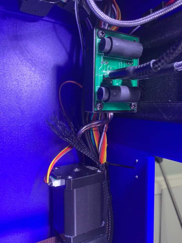
I made a small PCB board to go on the extruder and a distribution board to split can signal into two feeds.
by using USB C 3.2 i think I can supply ennough current at 24V
if anyone is interested I could share the designs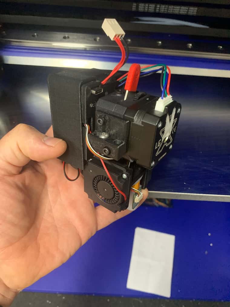
-
Hot swap 1LC toolboardposted in General Discussion
so the question is - is it possible to restart the board without cycling power?
for instance while printing you disconnect the toolhead and the board reports that CAN20 stopped sending signal
then you reconnect the toolhead, so the connection is restored, but the board doesn't see it.
is it possible to reconnect the toolhead without cyucling power? -
RE: Ghost can boardposted in General Discussion
@Phaedrux said in Ghost can board:
@Aurimas I understand you're frustrated, but being snarky to those trying to rule out basic things isn't going to get you anywhere here.
I am not frustrated - it has no affect on the machine performance.
I am simply reporting a bug in the firmware - I am not new to the system and I know how to use it.
if it dissapears with restart it makes no difference - the bug is still there even though it is not coming up all the time and it will not be fixed if left like this -
RE: Error: G1: intermediate position outside machine limitsposted in General Discussion
@dc42 just yesterday I had that issue, changed the Z minimum to allow negative value and it was printing since.
although it would be difficult to test your suggestion since the error didn't happen 100% of the time or in the same spot.
so my theory would be that if there is some inconsistency in the measurements at different spots of the bed it wants to compensate below minim and that is when it has fits.
It is always in the random spots on the bed (mostly well within limits) and not always - only sometimes. -
RE: Ghost can boardposted in General Discussion
@Phaedrux said in Ghost can board:
Have you tried a hard refresh of the browser by clearing the cache?
guys, seriously - I am pointing out a bug - ghost can address appears from nowhere
what is the point of refreshing page and/or doing anything to make it go away if it doesn't affect anything
It is not supposed to happen. PeriodI don't need suggestion such as restart the printer or refresh the browser
-
RE: Error: G1: intermediate position outside machine limitsposted in General Discussion
@droftarts All of the suggested kindergarten stuff has been done before asking for expert help in the forum
-
RE: Ghost can boardposted in General Discussion
@droftarts said in Ghost can board:
@Aurimas That usually means there's a reference in your config.g (or other macro) to a board at CAN address 119. I had something similar yesterday.
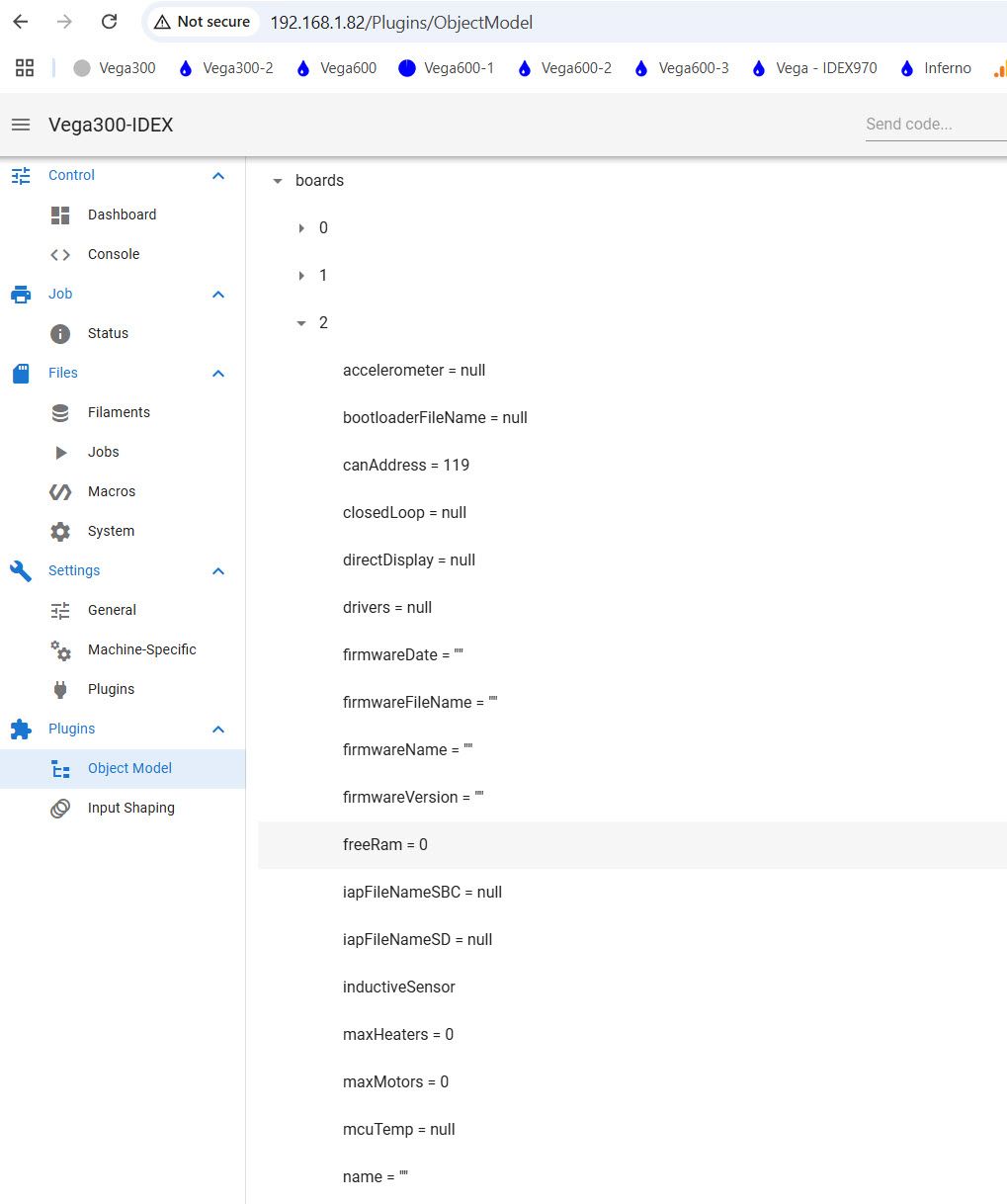
Object model plugin doesn't take data out of the config file - it scans hardware and reports the data.
but since you insist here is the config file - help youself out
on top of that - today there after powering up there is no ghost board; Configuration file for Duet 3 Mini 5+ (firmware version 3) ; executed by the firmware on start-up ; ; generated by RepRapFirmware Configuration Tool v3.2.3 on Sat May 08 2021 10:30:29 GMT+1000 (Australian Eastern Standard Time) ; General preferences G90 ; send absolute coordinates... M83 ; ...but relative extruder moves M550 P"Vega300-IDEX" ; set printer name G4 S1 ;wait for expansion boards to start ; Network ;M551 P"Vega" ; set password M552 S1 ; enable network M586 P0 S1 ; enable HTTP M586 P1 S0 ; disable FTP M586 P2 S0 ; disable Telnet M575 P1 S1 B57600 M584 X0.2 Y0.3 Z0.0:0.1 U0.4 E121.0:20.0 ; set drive mapping M669 K1 X1:1:0:0 Y-1:1:0:0 U0:0:0:1 Z0:0:1:0 ; select CoreXY mode ; Drives M569 P0.0 S0 D3 V40 ; physical drive 0.0 goes forwards M569 P0.1 S0 D3 V40 ; physical drive 0.1 goes forwards M569 P0.2 S1 ;D3 V40 ; physical drive 0.2 goes forwards M569 P0.3 S1 ;D3 V40 ; physical drive 0.3 goes forwards M569 P0.4 S0 ;D3 V40 ; physical drive 0.4 goes forwards M569 P121.0 S0 D3 V40 M569 P20.0 S0 D3 V40 M350 X16 Y16 Z16 U16 T1 E16:16 I1 ; configure microstepping with interpolation M671 X-125:465 Y170:170 S14 M92 X100.00 Y100.00 Z2400.00 U80.00 E400.0:400.0 ; set steps per mm M566 X1200.00 Y1200.00 Z20.00 U1200 E3200.00:3200.00 ; set maximum instantaneous speed changes (mm/min) M203 X15000.00 Y15000.00 Z280.00 U15000.00 E10200.00:10200.00 ; set maximum speeds (mm/min) M201 X3000.00 Y3000.00 Z20.00 U3000.00 E1550.00:1550.00 ; set accelerations (mm/s^2) M906 X1600 Y1600 Z850 U1200 E600:600 I30 ; set motor currents (mA) and motor idle factor in per cent M84 S90 ; Set idle timeout ; Axis Limits M208 X-65 Y0 U0 Z-1 S1 ; set axis minima M208 X325 Y340 U390 Z420 S0 ; set axis maxima ; Endstops M574 X1 S1 P"!io2.in" ; configure switch-type (e.g. microswitch) endstop for low end on X via pin M574 Y1 S1 P"!io3.in" M574 U2 S1 P"!io4.in" M574 Z1 S2 ; configure Z-probe endstop for low end on Z ; Z-Probe M950 S0 C"121.io0.out" ; create servo pin 0 for BLTouch M558 P9 C"121.^io0.in" H5 F2200 T3000 S0.25 ; set Z probe type to bltouch and the dive height + speeds G31 P300 X0 Y30 Z3.5 ; set Z probe trigger value, offset and trigger height Increase Z number if the nozzle is too far M557 X50:330 Y40:280 S200 ; Heaters M308 S0 P"temp0" Y"thermistor" T100000 B4138 ; configure sensor 0 as thermistor on pin temp0 M950 H0 C"out0" T0 ; create bed heater output on out0 and map it to sensor 0 M307 H0 B1 S1.00 ; enable bang-bang mode for the bed heater and set PWM limit M140 H0 ; map heated bed to heater 0 M143 H0 S120 ; set temperature limit for heater 0 to 120C M308 S1 P"121.temp0" Y"pt1000" R2200 ; configure sensor 1 as PT1000 on pin 121.temp0 M950 H1 C"121.out0" T1 ; create nozzle heater output on 121.out0 and map it to sensor 1 M307 H1 B0 S1.00 ; disable bang-bang mode for heater and set PWM limit M143 H1 S350 M308 S2 P"20.temp0" Y"pt1000" R2200 ; configure sensor 2 as PT1000 on pin 121.io0.in M950 H2 C"20.out0" T2 ; create nozzle heater output on 122.out0 and map it to sensor 2 M307 H2 B0 S1.00 ; disable bang-bang mode for heater and set PWM limit M143 H2 S350 ; set temperature limit for heater 2 to 350C M308 S4 P"temp1" Y"thermistor" T100000 B4138 ; configure sensor 2 as thermistor on pin temp2 ;M950 H4 C"out5" T4 ; create chamber heater output on out2 and map it to sensor 4 ;M307 H4 B1 S1.00 ; enable bang-bang mode for the chamber heater and set PWM limit M141 H4 ; map chamber to heater 2 ;M143 H4 S70 ; set temperature limit for heater 2 to 280C ; Fans M950 F3 C"20.out1" Q500 ; create fan 1 on pin 121.out2 and set its frequency M106 P3 S0 ; set fan 1 value. Thermostatic control is turned on M950 F1 C"121.out1" Q500 ; create fan 3 on pin 122.out2 and set its frequency M106 P1 S0 ; set fan 3 value. Thermostatic control is turned on M950 F5 C"out5" Q500 ; create fan 1 on pin out3 and set its frequency ;M106 P5 S1 H4 T55 ; set fan 1 value. Thermostatic control is turned on M950 F4 C"20.out2" Q500 M106 P4 T45 H2 M950 F2 C"121.out2" Q500 M106 P2 T45 H1 M950 P12 C"out1" M42 P12 S1 ;turn the light on M950 F10 C"out6" Q500 ; create fan 2 on pin out5 and set its frequency M106 P10 S1 ; set fan 2 value. Thermostatic control is turned on ; Tools M563 P0 S"Left Extruder" D0 H1 F1 ; define tool 1 M568 P0 S0 R0 A0 M563 P1 S"Right extruder" D1 H2 X3 F3 ; define tool 2 M568 P0 S0 R0 A0 ; ''' Create a tool that prints 2 copies of the object using both carriages''' M563 P2 S"Copy 200x340" D0:1 H1:2 X0:3 F1:1 L0; tool 2 uses both extruders, hot end heaters and fans, and maps X to both X and U G10 P2 X30 Y0 U-165 S0 R0 ; set tool offsets and temperatures M567 P2 E1:1 ; set mix ratio 100% on both extruders ;''' Create a tool that prints 2 copies of the object using both carriages''' M563 P3 S"Mirror 180x340" D0:1 H1:2 X0:3 F1:1 L0; tool 2 uses both extruders, hot end heaters and fans, and maps X to both X and U G10 P3 X50 Y0 U-370 S0 R0 ; set tool offsets and temperatures M567 P3 E1:1 ; set mix ratio 100% on both extruders ; Custom settings are not defined ; M591 D0 P3 C"121.io1.in" S1 R50:150 L24.8 E5.0 ; Duet3D rotating magnet sensor for extruder drive 0 is connected to E0 endstop input, enabled, sensitivity 24.8mm.rev, 70% to 130% tolerance, 3mm detection lengt ; M591 D1 P3 C"20.io1.in" S1 R50:150 L24.8 E5.0 ; Duet3D rotating magnet sensor for extruder drive 0 is connected to E0 endstop input, enabled, sensitivity 24.8mm.rev, 70% to 130% tolerance, 3mm detection length ; Miscellaneous M575 P1 S0 B57600 ; enable support for PanelDue M501 ; load saved parameters from non-volatile memory T0 ; select first tool M307 H0 R0.21 K0.586:0.000 D3.70 E1.35 S1.00 B1 -
RE: Changing Stepper Speeds Dynamically with Duet wifiposted in MultiAxis Printing
@eranglr said in Changing Stepper Speeds Dynamically with Duet wifi:
ommand to change the steps/mm for each axis, effectively
segmentation most likely is not going to work since you will ahve jerk and accelleration to take into account.
I have done similar thing before and you have to account for those factors. -
Ghost can boardposted in General Discussion
3.5.4 version
the board CAN address appears from nowhere.
there is nothing in config or anywhere else.
seen this few times now - after restarts too
the board is listed under machine specifics and object model show the ghost board too. Images attached.
rest of the boards are perfectly fine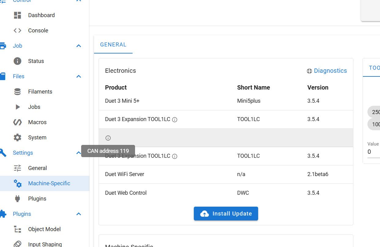
-
RE: Error: G1: intermediate position outside machine limitsposted in General Discussion
@droftarts @T3P3Tony @dc42 is it possible that bed mesh compensation might be creating this issue in the latest firmware versions?
For instance if Z axis min is set to 0 and the bed mesh has to go to -0.2mm or similar - would that throw an error? -
RE: Filament drive counting backwardsposted in Duet Web Control
@dc42 just as suspected
")
filament counter is counting correctly anyway. -
RE: Filament drive counting backwardsposted in Duet Web Control
@T3P3Tony @dc42 it doesn't really affect anything - I am just reporting that there is something in the code that is doing that.
thanks -
RE: Filament drive counting backwardsposted in Duet Web Control
@T3P3Tony said in Filament drive counting backwards:
t the step counter is overflowing hence
its only 400/mm
-
RE: Filament drive counting backwardsposted in Duet Web Control
@dc42 no sure why would steps matter?
Filament counter reports correctly, while Extruders Drives got inverted mid print
These are two different counters from what I understand and because of that it has software setting issue -
RE: Filament drive counting backwardsposted in Duet Web Control
@T3P3Tony yes - it was correct to start with.
I am not sure at what point it flipped -
RE: Filament drive counting backwardsposted in Duet Web Control
@magnets99 said in Filament drive counting backwards:
you could probably lost pla cast a whole engine block with that!
Reply
lol. it would depend on the size of the engine block