PT100 vs Thermocouple Duet Daughter Boards
-
Hi,
Looking for a better temp sensing solution for my hotend, I came across 2 equally priced options in the Duet product line, namely:
K type Thermocouple Daughter Board
I have a basic grasp of the difference in the underlying architecture between these 2 types of temp sensors, and at least according to this (randomly googled) source, it seems a thermocouple would be more suitable for the hotend, but I was hoping those with experience could further enlighten me on the advantages/disadvantages of choosing one over the other in this context.
Also, I wanted to ask if the latest schematics & board layout design of these daughter boards (ver. 1.1 I think) are available online? and, if so, where might I find them?
Thanks!
SnowCrash -
I use a PT100 on my main printer, and I have just gotten a PT1000 (no amplifier board needed).
While a thermocouple might have faster temperature response, I like the PT100 and it is definitely not prone to breakage on a printer.
PT100 is calibrated to have 100 Ohms at 0 C, while a thermocouple has to be calibrated (think ice bath) against another already calibrated thermocouple - however it wouldn't hurt to confirm resistance on a PT100 either.
Thermocouples are prone to noise because the signal is a voltage signal and can change quickly.
An RTD (like PT100) can be affected by the length of wire because it can subtly increase resistance (hence why I want to try a PT1000 - precision piezo sells some) - although if they came with four wires you could actually compensate for the resistance - but alas they do not for printers.
-
@zzing you can still splice the two leads of the PT100 sensor into 4 seperate wires and get the benefit.
-
Have you seen https://duet3d.dozuki.com/Wiki/Temperature_sensors ?
-
@snowcrash I would suggest you always use a PT100 unless you need to use a thermocouple because the PT100 has greater noise immunity and much easier to wire through various connectors.
Your question prompted me to check and the v1.1 of the boards wwre not shared on Github so I have updated that:
https://github.com/T3P3/TempDaughterboards -
Thermocouples are great, simple, and robust if you obey a few simple “gotcha” rules...
- No TC wire splicing unless you use more type-K TC wire and proper type-K plugs. The TC doesn’t actually measure tip temperature, it measures the difference in temperature from one end of the wire pair to the other. So the TC wire needs to run all the way to the Duet. There ARE plugs and extension wires available but you CANNOT use copper.
- Avoid running TC wires parallel to EM noise sources like untwisted motor or heater wiring. (This is good practice with thermistors and PT sensors too.)
- If the temp reads negative, flip the leads.
- One type-K wire is magnetic and one is not. This helps splice and terminate TC wire when the insulation color coding is inconsistent. (Different countries use different color standards.)
- Keep the tip electrically insulated from the hot block.
- Be careful of wire fatigue.
The great thing about TCs in my view is that they’re just two-conductor wire with the tips touching... you can cut a thermocouple in half, strip and twist the tips, and now you have two thermocouples. It’s guaranteed to work and sense within about 2C accuracy by the metallurgy of the wires. There’s no magical and opaque at the tip that you have to worry about.
-
First of all, a big thank you to everyone who responded and all the very useful information and advice! Got exactly what I was looking for and more

I decided to go with a PT-100 in a 4-wire arrangement coupled with an amplifier board.
The combination of eliminating wire resistance (I've got a delta so the wires are fairly long), coupled with no need for calibration are the big selling points for me. I plan on using a shielded dual twisted pair cable for this setup so that would hopefully minimize interference as well.
Btw, for the benefit of anyone else who might be looking for info on this, I came across @dc42's excellent write-up on the daughter board here. It refers to a much earlier version of the board, but nevertheless was very helpful in getting a better understanding of how things work.
And speaking of which, while studying the schematics for the daughter board (thanks @T3P3Tony!), I think I may have spotted a tiny inconstancy between these schematics and the official Duet pinout diagram.
As you can see in the image below, the pin labeled CS_1 on the daughter board seems to be named SPIO_CS0 in the diagram:

Lastly, a quick follow-up question:
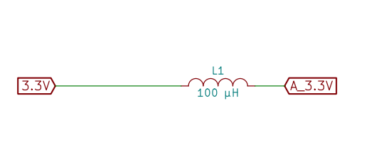
Can anyone tell me what's the part number of the 100uH inductor (L1) on the daughter board? or at least the current rating of this part?

Thanks again for the great comments! much appreciated everyone!
-
You are right - the pin labeled SPI0_CS0 is actually CS1. I'll ask Tony to change it.
The current rating of L1 is not critical because the MAX31855 chips only draw up to 3.5mA each.
-
Thanks, @dc42. I figured as much, but wanted to make sure

-
@snowcrash thanks, fixed.