Sovol SV08 Multiple Motion System Upgrade.
-
My response to Advantages and disadvantages of Dual Gantry over IDEX and Tool changers as asked by @MostlyMessingAbout
Advantages of Dual Gantry over IDEX
- Additional degree of freedom in Y Axis - allows for parallel printing of different shaped parts or whole objects (if independent Z hopping also available). - up to doubling print speeds.
- Allows Parallel priming and wiping during tool changes - which can push tool change times from >10 seconds down to <1 second
- Only having one head on each gantry means faster speeds possible in the Y direction in particular - which can be an issue with IDEX
- When used in combination with IDEX can allow up to 4 toolheads which can all print in parallel for some parts of large prints. - which could increase print speeds by over 50% more.
- Print head can access the whole X axis
Disadvantages of Dual Gantry over IDEX
- Increased complexity of belt routing
- Slicers don’t currently support parallel printing - so post processing of GCODE required
- Print heads cannot individually access the whole Y axis
- The front gantry and print head can block the view of the rear gantry.
Advantages of Dual Gantry over Tool changing
- Parallel printing - up to doubling print speeds.
- Allows Parallel priming and wiping during gantry or tool changes - which can push tool change times from >17 seconds down to <1 second
- When used in combination with IDEX can allow up to 4 toolheads which can all print in parallel for some parts of large prints. - which could increase print speeds by over 50% more.
- When used in combination with tool changing would allow extremely fast tool changes if the tool changes occur between the two gantries
- Less equipment sitting around not being used 90% of the time.
Disadvantages of Dual Gantry over Tool changing
- Increased complexity of belt routing
- More motors if using a Nozzle changer tool changer
- Slicers don’t currently support parallel printing - so post processing of GCODE required
- Print heads cannot individually access the whole Y axis
- The front gantry and print head can block the view of the rear gantry.
In response to question from @JavierHernandez-bj5hz asking where the Quad head design will be CoreXYUVAB
The current 2 head dual gantry implementation is already CoreXYUV, with AB added on for independent Z lifting.
When I move to 4 head IDEX I will be changing the kinematics of each Gantry over from CoreXY to Dual Markforged - So I guess it will be something like Double , Dual Markforged, Might be Better to call it Quad Markforged I suppose/
In terms of AXIS it will have Z0, X1,Z1,Y,X2,Z2, U1,Z3,V,U2,Z4.
Which in RRF will be XYZUVABCDEF.Then just to add to the complication - the next phase after IDEX is 'occasionally moving bed' - which will add a additional larger Y axis movement capability - so will then be
Z0, X1,Z1,Y,X2,Z2, U1,Z3,V,U2,Z4, Y2 , Which in RRF will be XYZUVABCDEFG -
@o_lampe If you look at some of my earlier video's you might see something like that.
Interestingly if I do end up with a fairly long bed - maybe 600 or 700 mm - then I might have to consider getting a 2nd SV08 and bolting it on the front - which as you said could have 4 heads of its own.
Might get out of hand though.
I think I will probably stop at 3 heads for a while - so that I can see how beneficial adding the 3rd IDEX head really is in real life situations.
I would though really think something like an Orangestorm Giga (with the 1m x 1m x 1m). Could really benefit from 3 gantries with 2 or 3 heads on each, or maybe even 4 gantries with 2-4 heads on each.
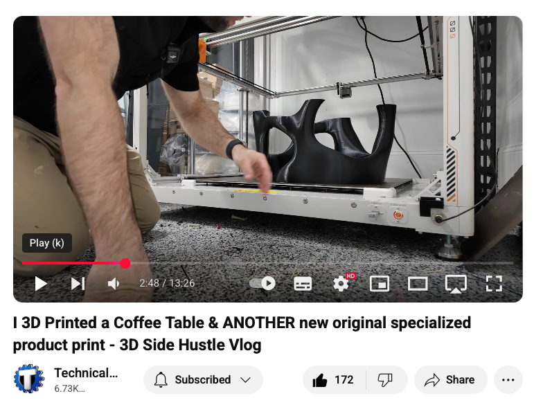
There was a good example in this video of printing a coffee table - where the 4 legs could be printed in parallel quite easily.
-
@dwuk3d said in Sovol SV08 Multiple Motion System Upgrade.:
Z0, X1,Z1,Y,X2,Z2, U1,Z3,V,U2,Z4, Y2 , Which in RRF will be XYZUVABCDEFG
Just call it Alphabet kinematics , because there aren't many unused letters left
")
-
@dwuk3d said in Sovol SV08 Multiple Motion System Upgrade.:
In response to question from @JavierHernandez-bj5hz asking where the Quad head design will be CoreXYUVAB
The current 2 head dual gantry implementation is already CoreXYUV, with AB added on for independent Z lifting.
When I move to 4 head IDEX I will be changing the kinematics of each Gantry over from CoreXY to Dual Markforged - So I guess it will be something like Double , Dual Markforged, Might be Better to call it Quad Markforged I suppose/
In terms of AXIS it will have Z0, X1,Z1,Y,X2,Z2, U1,Z3,V,U2,Z4.
Which in RRF will be XYZUVABCDEF.Then just to add to the complication - the next phase after IDEX is 'occasionally moving bed' - which will add a additional larger Y axis movement capability - so will then be
Z0, X1,Z1,Y,X2,Z2, U1,Z3,V,U2,Z4, Y2 , Which in RRF will be XYZUVABCDEFGThanks David, I called it TotalPnP QuadMarkForged. I not design a 3D printer,actually I design desktop SMT (PCBA) machines. And I have some interesting ideas with this.
So, would duplicating the Dual Markforged IDEX kinematics be enough?
What do you think about using GT2 50T timing pulley instance 20T timing pulley in motors? I have been using it like this in both Y and X for years with Nema17 60mm in cartesian machine and it has worked well for me. You lose a little torque but you gain some speed, and since they are 60mm there is still enough torque to work well.
Best regards
Javier Hernandez
-
@bricobot not sure about 50t - I guess having two motors on the dual Markforged Y axis does mean there should be plenty of torque - so I could look at increasing speed.
What i would like to do is get close to SV08 standard single head speeds - which I think is fairly quick -but then double or triple this with parallel printing.
Then make colour changes between 10 and 100x quicker than any non parallel printer.
-
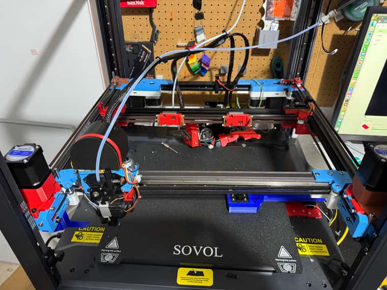
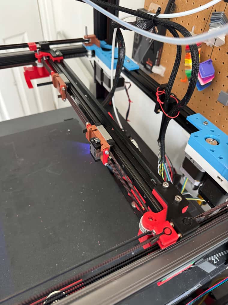
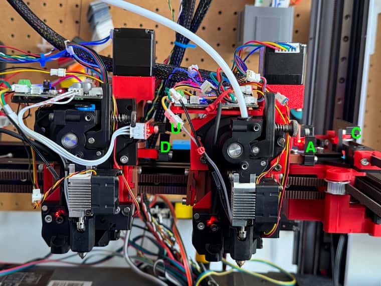
Rear gantry IDEX all belted and motor'd up - just need wiring and software now - plus rebuilding of 3rd extruder
-
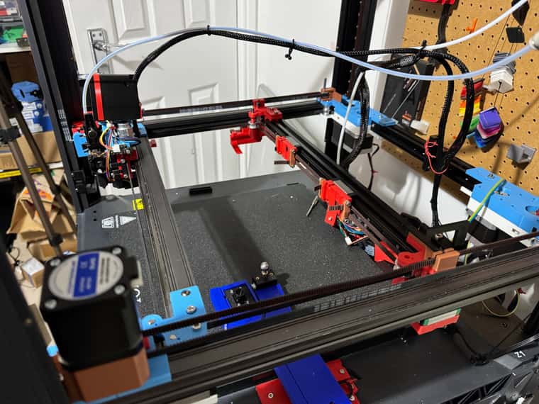
IDEX on rear gantry moving OK.
I've wired up the two extra Y motors as the C Axis - by then used M669's to convert that over to be the V axis
To move the V axis - you need to move the two new motors, plus also the two existing U + V motors.
I thought it was going to be tricky - but seems to be working surprisingly well.
Will have to do something about independently homing the two new V axis motors - to make sure that the gantry is properly at 90 degrees.
But overall quite happy so far - just need to build the 3rd extruder now and add few end stops - before working on the homing macro's + alignment etc.
; Smart Drivers M569 P0.0 S1 D2 ; driver 0.0 goes forwards (Z axis) M569 P0.1 S1 D2 ; driver 0.1 goes forwards (Z axis) M569 P0.2 S0 D2 ; driver 0.2 goes backwards (Z axis) M569 P0.3 S1 D2 ; driver 0.3 goes forwards (X axis) M569 P0.4 S0 D2 ; driver 0.4 goes backwards (Y axis) M569 P1.3 S1 D2 ; driver 0.5 goes backwards (Z axis) - changed to 1.3 forwards ;M569 P1.0 S0 D3 V2000 ; driver 1.0 goes backwards (U axis) ;M569 P1.1 S0 D3 V2000 ; driver 1.1 goes backwards (V axis) M569 P1.0 S0 D2; driver 1.0 goes backwards (U axis) M569 P1.1 S0 D2 ; driver 1.1 goes backwards (V axis) M569 P1.4 S0 D2 ; Z-hopper 2 M569 P0.5 S1 D2 ; Z-hopper 1 M569 P1.5 S0 D2 ; VH Axis Left M569 P1.6 S1 D2 ; VH Axis Right M569 P121.0 S0 D2 ; driver 121.0 goes backwards (extruder 0) M569 P122.0 S0 D2 ; driver 122.0 goes backwards (extruder 1) ; Motor Idle Current Reduction M906 I30 ; set motor current idle factor M84 S30 ; set motor current idle timeout ; Axes M584 X0.3 Y0.4 Z0.1:0.2:0.0:1.3 U1.0 V1.1 A1.4 B0.5 C1.5:1.6; set axis mapping M350 X16 Y16 Z16 U16 V16 A16 B16 C16 I1 ; configure microstepping with interpolation M906 X800 Y800 Z800 U800 V800 A750 B150 C800 ; set axis driver currents ; A - 1.8 degree, 0.7mm pitch - 200*16/0.7 = 4571 ; A - 1.8 degree, 1mm pitch - 200*16 = 3200 M92 X80 Y80 Z533.33 U80 V80 A3200 B629 C80 ; configure steps per mm if exists(global.vMin) == false global vMin = 120 global vMax = 340 global yMin = -5 global yMax = 210 M208 X-5:310 Y-5:210 Z0:300 U3:326 V120:334.7 A0:3 B0:3 C120:334.7; set minimum and maximum axis limits M566 X540 Y540 Z100 U540 V540 A500 B300 C540 ; set maximum instantaneous speed changes (mm/min) M203 X{350*60} Y{350*60} Z{25*60} U{350*60} V{350*60} A1000 B200 C{350*60} ; set maximum speeds (mm/min) M201 X2000 Y2000 Z500 U2000 V2000 A1000 B20 C2000 ; set accelerations (mm/s^2) ; Extruders M584 E121.0:122.0 ; set extruder mapping M350 E16:16 I1 ; configure microstepping with interpolation M906 E800:800 ; set extruder driver currents M92 E492:492 ; configure steps per mm M566 E120:120 ; set maximum instantaneous speed changes (mm/min) M203 E{30*60}:{30*60} ; set maximum speeds (mm/min) M201 E250:250 ; set accelerations (mm/s^2) ; Kinematics ;M669 K8 ; configure CoreXYUV kinematics M669 K1 ; configure CoreXY kinematics ; X:Y:Z:U: V:A:B:C M669 V0:0:0:1:-1:0:0:1 M669 C0:0:0:0:01:0:0:0 -
@dwuk3d said in Sovol SV08 Multiple Motion System Upgrade.:
M569 P1.3 S1 D2 ; driver 0.5 goes backwards (Z axis) - changed to 1.3 forwards
When CanFD was new to RRF, it was a golden rule NOT to spread drivers from the same axis across different boards, but I guess the timing/lag issues are now under control?
-
@o_lampe Good spot - I did think that might be an issue - particularly with multiple motion systems - but I haven't noticed any problems so far.
I wanted XY & B (the zHopper for X) to be on the same board - and there wasn't room on the 6HC for all 4 Z Axis.
I suppose I should really swap everything around and have the rear gantry on the 6HC as U V1 V2 C(u2) A(zhU) D(zHu2)
Then the front Gantry and Z on the 7 way Mini5+. X Y Z1 Z2 Z3 Z4 B(zhX)The 6HC and Mini5+ have different size connectors for the motor drivers which adds to the complication.
-
@dwuk3d I'm not sure if this is still an issue anyway.
But when you use two motors on the same belt, it might not be a good thing if they don't move super-synchronous. Worst thing would be loosing steps, when the motor who's trying a headstart is too weak to power through. -
It moves......
Next step - wire up 3rd extruder with 1LC tool board.
Then some more end stops and homing.
-
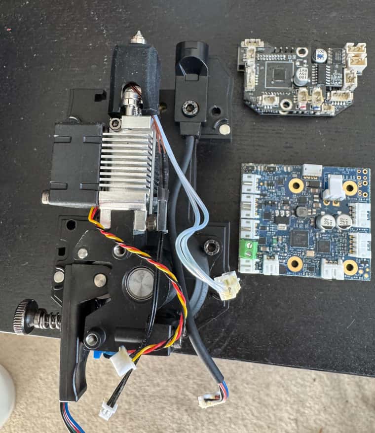
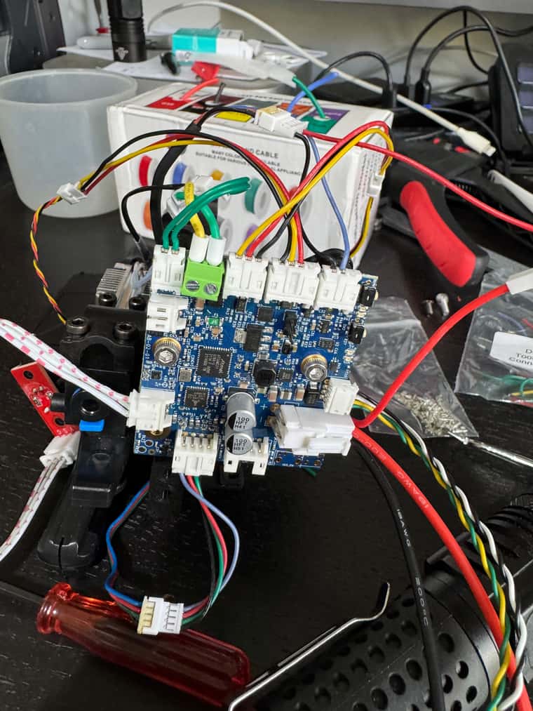
Starting on wiring up the 1LC on the last extruder.
Horizontal placement of the board above the extruder is not that neat - but I guess the for left hand extruder the overlap isn't a big issue.
For the other two extruders I made up adaptors - to make the upgrade reversible - I think for this one I will take a different approach - and cut and replace the connectors on any cables that are long enough - as likely to have two spare extruders once I do the INDX upgrade even if I end up trying a Klipper version later.
-
@dwuk3d All wired up

-
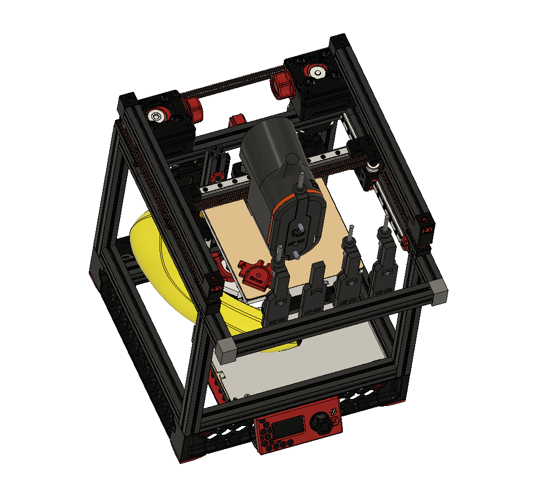
Updated my CAD for INDX a bit based on latest pictures, plus created a Voron Zero version.


-
Almost ready to start trying homing.
Decided to home the left extruder on the right extruder - mainly so that can use an identical design for two extruders.
So right extruder will need to be homed first on the gantry.
Also doubled up on end stops again - so single optical sensor left extruder for U axis (X) (homing on to other extruder) , D Zhopper, then another single optical sensor for right extruder - C axis (X) and A Zhopper.
Will probably have to rationalise the axis letters at some point.
Used an M4 bolt again for lead screw on left extruder as need to order some more lead screw nema 11s.
-
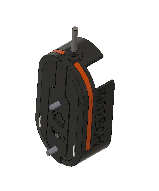
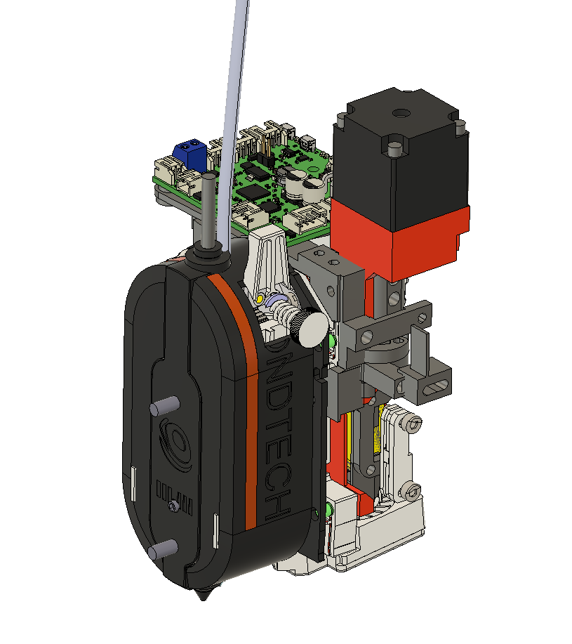
Rough scale of Bondtech INDX toolhead overlaid over my current SOVOL toolhead.


-
@dwuk3d The main negative I can see of the Bondtech INDX that I can see is that the nozzle is far forward, away from the X axis and carriage. This is understandable given the layout, but I think it will mean losing some Y axis, or mean that the bed will have to move towards the front of the printer for full coverage.
Ian
Bed-slinger - Mini5+ WiFi/1LC | RRP Fisher v1 - D2 WiFi | Polargraph - D2 WiFi | TronXY X5S - 6HC/Roto | CNC router - 6HC | Tractus3D T1250 - D2 Eth
-
@droftarts Your input just started a long train of thought, but it's not related to this thread.
[OT]
The almost forgotten screw-extruder was build as DD extruder (hollow shaft a.s.o.) but with a bit of modification it could become a super compact tool changer, similar to the INDX. Plus it wouldn't need hollow shaft motors anymore.(no filament softening issues! ) -
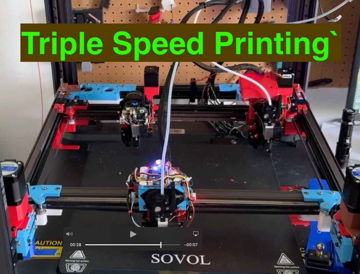
First proper three headed print.
Some work required on alignment, purging and speed - but quite pleased with results so far.
Gantry 1 and 2 are running on different motions systems - and very slightly in parallel.
https://youtu.be/4TYAep9QcUE
Three colour build area a little bit restricted - so need to get the print heads a little bit smaller...
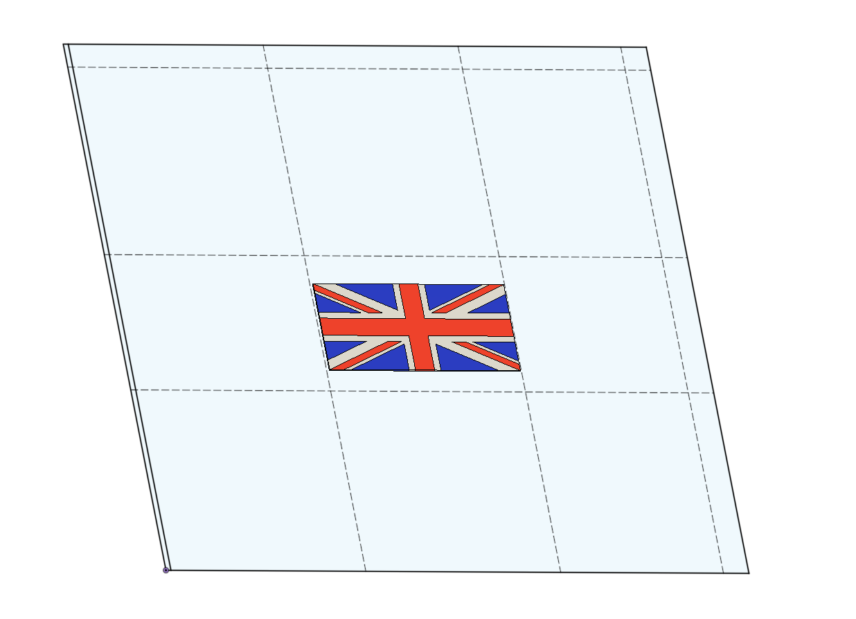
NB/ Flag on printer is 70% of this scale - so could print a slightly bigger one.Changed over C gantry to be W as missing out a letter caused problems with tools definitions.
Also put V motors on correct AxisKinematics now simply the following
M669 K1 ; configure CoreXY kinematics ; X:Y:Z: U: V: W:A:B:D M669 V0:0:0: 1: 1:-1:0:0:0 -
@dwuk3d said in Sovol SV08 Multiple Motion System Upgrade.:
Changed over C gantry to be W as missing out a letter caused problems with tools definitions.
Missing out a letter should not matter. What might matter is that in the M584 command that creates the axes, C default to rotary but W defaults to linear.
Duet WiFi hardware designer and firmware engineer
Please do not ask me for Duet support via PM or email, use the forum
http://www.escher3d.com, https://miscsolutions.wordpress.com