Capacitive PNP Sensor Connection Query
-
Good morning @dc42,
I have a question regarding the wiring of a normally closed PNP capacitive sensor that I intend to use for material detection in my headstock. This sensor will operate at 24V, and after reviewing the documentation, it recommends using a voltage divider with a 2.2K resistor (R2) and a 10K resistor (R1). However, I am using the Duet 3 Mainboard 6HC and Duet 3 Mainboard 3HC, which specify that sensor inputs are tolerant up to 30V. My question is whether I can avoid using these resistors and connect the sensor directly to my Duet.
Considering that my headstock has electronics designed by me, the 24V powering my sensor would come from V_FUSE. The ground terminal (GND) would be connected to the IO_# inputs, and the signal would be connected to io#.in.
I appreciate any guidance you can provide on this matter.
Best regards,
-
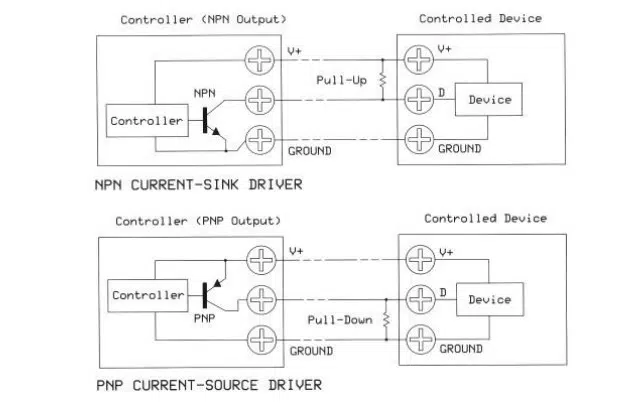
@Aitor you will need a pulldown resistor at the very least. To avoid excessive power dissipation in the pulldown resistor, and to protect the system if you make a wiring error or get a short circuit on the connector, we recommend using the potential divider.
If you have the choice, we recommend choosing an NPN-output sensor.
-
Good morning, @dc42,
Thank you for your response. Why do you recommend the use of an NPN sensor? I understand that I still need to place a resistor as shown in this diagram, correct?

Regards,
-
@Aitor the IO_IN inputs of the Duet already include a pullup resistor.