Position change after mesh bed compensation (G29)
-
My mesh compensation (G29) always ends in position X1 Y629 (left rear corner). How can I change that so that it ultimately moves to position X10 X10?
-
@axiom you could use mesh.g to do custom things before/after the actual mesh probing
-
If you create a file mesh.g. any code you put in it will be executed when you do a G29 with no S parameter.
I put everything related to creating the height map in mesh.g
For example here is a simple version:
M557 Xaaa:bbb Yccc:ddd Pee:ff ; define the probing grid

G90         ; absolute moves
G1 X0 Y0    ; move to bed center (which is where I move to set the Z=0 Datum)

G30         ; do a single probe to set the Z=0 Datum

G29 S0      ; probe the bed and create the height map

G90         ; absolute moves
G1 X10 Y10  ; move to desired location
Frederick
-
@jay_s_uk Unfortunately I don't have a mesh.g file in my system files. By the way, what is the difference between G29 and G32?
-
@axiom Oh I saw fcwilt's reply too late....thanks! But again when do I use the G29 command and when the G32? Unfortunately, I can't do anything with the translation into my language
-
@axiom G29 is for mesh levelling (scanning the whole bed), see https://docs.duet3d.com/en/User_manual/Reference/Gcodes#g29-mesh-bed-probe
G32 is for running the bed.g macro, see https://docs.duet3d.com/en/User_manual/Reference/Gcodes#g32-run-bedg-macro. This can be used for a number of different bed levelling/calibration tasks, like levelling a bed on 3 independent motors, or calibrating a delta printer.Also covered here: https://docs.duet3d.com/User_manual/Connecting_hardware/Z_probe_auto_probing
Ian
-
@axiom said in Position change after mesh bed compensation (G29):
@axiom Oh I saw fcwilt's reply too late....thanks! But again when do I use the G29 command and when the G32? Unfortunately, I can't do anything with the translation into my language
To use them as intended:
- G29 runs mesh.g
- G32 runs bed.g
The file mesh.g is associated with the feature known as Mesh Bed Compensation. This feature tries to compensate for bed irregularities during printing. The file should contain the commands needed to probe the bed and create the height map.
The file bed.g is associated with the feature known as Bed Leveling, though as discussed it should be termed Bed Tramming and you may see folks refer to it that way. The file should contain the commands needed to probe the bed and "level" it using either automatic or manual modes. Manual Mode requires 2 or more "thumb screws" which can raise/lower the bed at different points around perimeter of the bed, say, Left Rear, Center Front, Right Rear. Automatic Mode requires 2 or more Z steppers and the replaces the manual adjustment of the thumb screws with automatic adjustment of the Z steppers.
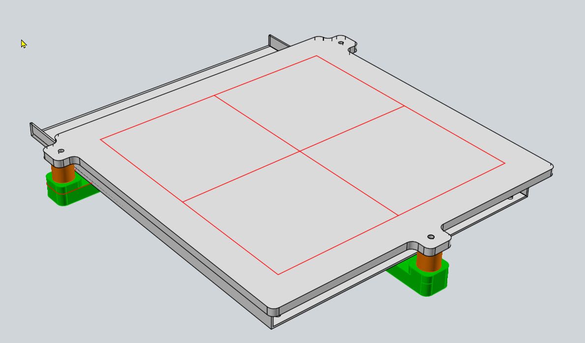
Here is an image of a new bed that is being fitted to one of my printers. The three "tabs" extending from the main bed area are where the three thumb screws attach to level the bed when using Manual Mode:

Here is a quick-and-dirty video showing my printer which is fitted with 3 Z steppers for auto leveling:
Automatic Bed Leveling Demonstartion
Frederick