Is Input Shaper not working or what's causing ringing?
-
Here's another test. Same settings (200mm/sec) but I rotated the model so the seam face was straight on the y-axis.
Somehow Prusa changed the seam when I rotated so the model with the full seam is identical to the 200mm/sec one above, just rotated. This was to see if orientation would have an impact.
The other print also had identical settings but I commented out the M593 command from config.g and restarted before printing.
So that should be without any Input Shaping at all.If there is any real differences between the prints it's so minor it's neglectable.
I'm out of ideas now, feels like I've tried everything, new original Gates belts, belt tension, with or without Mesh, different speeds, different IS, different acceleration, different orientations, different PA values but nothing seams to help.
-
@Reine See notes here: https://docs.duet3d.com/User_manual/Reference/Gcodes#notes-123
Input shaping not working for your printer? Check this:
- High X and Y jerk values are an issue for all types of Input Shaping because the theory behind IS assumes no jerk. Therefore you should set the X and Y jerk limits only as high as necessary to allow curves to be printed smoothly. Users report jerk values of 5mm/s (300mm/min) seem to allow for IS to work, and curves to print smoothly, though test it works for you.
- Another cause of IS not working is mesh compensation with a fine mesh and low acceleration. This splits the acceleration and deceleration parts of a move across multiple segments, which makes it difficult for RRF to apply IS.
- A third cause is short accelerate/decelerate moves.
Your jerk value is set to 300mm/min in motors_default_speed.g. Try halving this and see if it makes a difference. The initial jump may be the cause of the ringing, and IS can't account for it, because it has already happened.
Turn off any mesh compensation for one test, to see if that makes a difference.
I don't think the third option is relevant, unless you have set up segmentation in the M669 command, which I can't see that you have in your config.g.
Ian
-
@droftarts I've fiddled with Jerk between 1-5 with not much difference, but I'll give it another go.
Shall I limit X & Y only or also E?
-
@Reine Just X and Y. The extruder moving shouldn't cause ringing in the frame, I'd have thought.
Ian
-
@droftarts here we go.
https://imgur.com/a/gahSFnm -
@Reine the higher frequencies (e.g. 80Hz and above) may not be ringing at all, they may be vibrations caused by fans. Here is what I suggest:
- Have you tried printing without mesh bed compensation, so see whether the move segmentation that causes is a factor?
- Try reducing the input shaper centre frequency to about 41Hz to target the main peak.
-
@dc42 yes I have tried without mesh, but didn't notice any big difference.
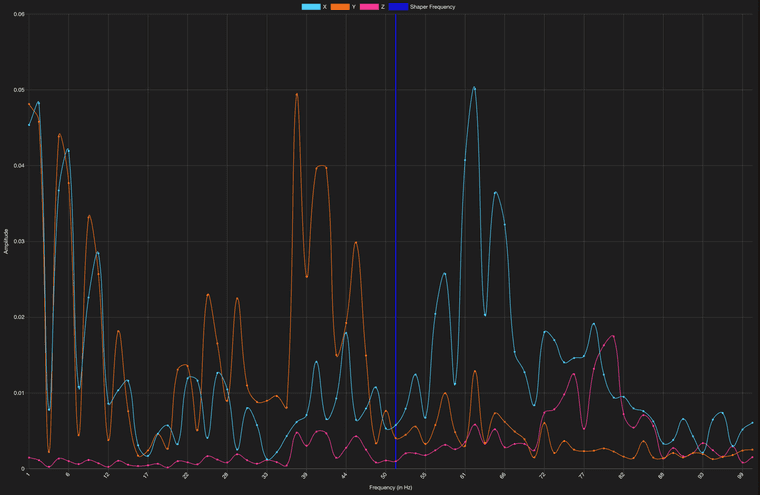
Can you help me understand how to use the IS graphs? Shall I capture data through the move or not?
Also, if I capture 5 datasets all graphs will be different, similar but different. Some can be more different than similar sometimes.
Capture data during the whole length of the move: ON
Capture data during the whole length of the move: OFF
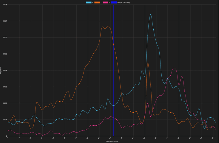
Depending on which the needed center frequency seams to change, which to me seams a bit wired?
-
I printed a ringing test which was configured to increase speed six times. From bottom we have:
30, 50, 100, 150, 200 & 250No other settings were changed since earlier examples.
Jerk is still at 2.5 on both x & y, acceleration 3k.Video of the result:
https://imgur.com/a/ilIudF4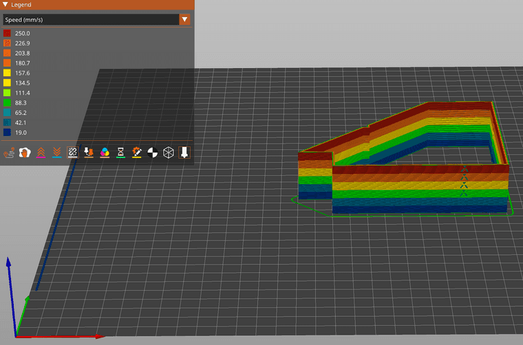
-
@dc42 check this out, I've recorded 14 IS graphs with no shaper configured to get a baseline and see how consistent readings I can get.
Notice the difference on the last 4 images, only thing I did was to restart the 6HC. Printer is in another room, nothing was printed and no one touched it. It's like 1min between those graphs.
I can not wrap my head around how to set this up.
-
@Reine I wonder why your graphs are so unstable, I am really worried you aren't measuring the right frequencies or your printer has some build issues we haven't figured out yet.
-
The testing continues. Today I've been using the Voron ringing tower.
In this example I've added a script that changes IS every 5mm in PrusaSlicer. It starts off with none, then goes to zvd 20 and increments by 5 until it reaches 70. Dampening 0.1.
Mesh is off and Pressure Advance is also off.
I've confirmed all settings while printing, even that IS is changing (with M593) and it's all correct.It's printed in vase mode, 225mm/sec & 4k accl, Jerk 2 as those were the best settings I found yesterday.
But as you can see in the video, there's no difference (what I can tell) between no IS, zvd@20 and zvd@70.
Something else must be interfering so it's not even working?
I've even printed one tower with all shapers at the same hz and couldn't tell much of a difference if any at all.
RRF 3.4.6.
https://imgur.com/a/tC5WESD@dc42 any ideas?
-
@Reine What steppers are you using? What amperage are they rated for? And what motor current are they set for in your M906 command? We've seen artifacts that, at first glance, appeared to be ringing only to discover it was due to underpowering the steppers..
-
@oozeBot LDO-42STH48-2504AC I've tested between 1.6 - 2A, think they are rated to 2.5.
-
-
When we switched to a variant of the 2504 steppers, one of our machines was showing signs of ringing not present on others, which led us on a bit of good chase. It was never as pronounced as Op’s example though (photo below). What it turned out to be was the config on that machine still had the values for the 2004 steppers at 1750 mA.
We run the class H (High Temp) model of the 2504 steppers and set them to 2250 mA while in operation. That’s high, but they can take it without issue and our 6HC main boards are actively cooled.
 image url))
 -
This post is deleted! -
@oozeBot I've upped my steppers to 2A, can't see much difference in temp on the 6HC but the steppers are slowly going up, not sure how high though as I haven't printed anything big yet.
What's a safe temp reading on their outer casing?
-
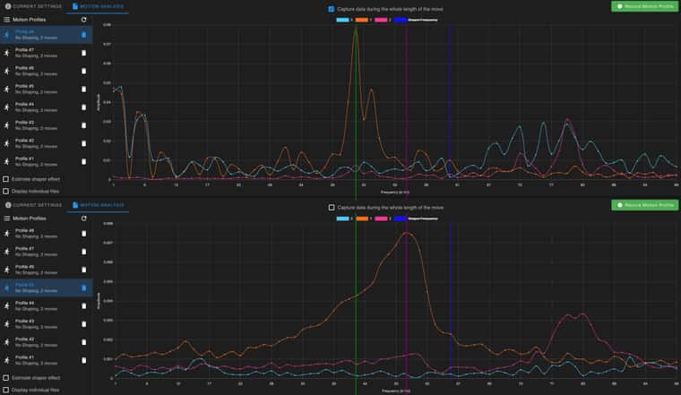
These two graphs are taken just minutes apart -- explain to me why they are so different and why the peak is not at the same frequency?
-
@Reine Just to be clear (in case others don't spot it), one set has the "capture data during entire move option" check on one but not on the other. This means you will be collecting data that includes motor vibration etc. on one but not on the other. I think the theory is that it is better to collect data after the move so that what you see is the resonance induced by the impulse but I'm no expert. The other thing to note is that the scales on the two graphs are very different (an order of magnitude), so the "peaks" in the second graph will be down in the noise of the first. Personally I don't really like the mechanism used to collect resonance data by RRF (I think the Klipper approach of basically sweeping a set of vibrations over the range, produces a stronger set of readings).
But I'm not sure the different readings you show relate to the print artefacts you are seeing. Though perhaps the fact that you get a 10x higher peak with the motors active is significant?
Looking at your earlier posts it would seem from the graphs in your first post that IS is having some impact on the resonances being shown. But perhaps those are not the cause of the artefacts you are seeing? What seems a little odd to me in the photos is that the "ringing" seems to be very spaced out (which may indicate a very low frequency) compared to what I've seen in other cases. Did you ever try estimating the frequency manually? See: https://www.klipper3d.org/Resonance_Compensation.html for a way to do this.
-
@gloomyandy I haven't used Klipper but that approach seams better to me too, an option to do X scans and average out the result and remove outliers would be a step in the right direction for the IS plugin imo.
Good point, the magnitude axis should haven an option to be fixed so it's easier to compare.
I did do the math now and came up with about 45Hz, it's lower than the graphs but not by much so that seams about right.
The ei3 print just finished and here is a comparsion with the zvd print I did earlier. Finally a difference, sadly still no change in the Hz range it's testing.
;AFTER_LAYER_CHANGE
{if layer_z >=  0}M593 P"ei3" F35 S0.1{endif}
{if layer_z >=  5}M593 P"ei3" F37 S0.1{endif}
{if layer_z >= 10}M593 P"ei3" F39 S0.1{endif}
{if layer_z >= 15}M593 P"ei3" F41 S0.1{endif}
{if layer_z >= 20}M593 P"ei3" F43 S0.1{endif}
{if layer_z >= 25}M593 P"ei3" F45 S0.1{endif}
{if layer_z >= 30}M593 P"ei3" F56 S0.1{endif}
{if layer_z >= 35}M593 P"ei3" F58 S0.1{endif}
{if layer_z >= 40}M593 P"ei3" F60 S0.1{endif}
{if layer_z >= 45}M593 P"ei3" F62 S0.1{endif}
{if layer_z >= 50}M593 P"ei3" F64 S0.1{endif}
{if layer_z >= 55}M593 P"ei3" F66 S0.1{endif}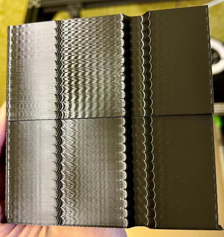
(zvd bottom, ei3 on top)Here's the gcode for that print, is there some issue in it preventing IS to update after each 5mm segment?
acceleration_test_piece_0.2mm_PLA_24m.gcode