JoergS5's CoreXY 5 axis (robot kinematics)
-
I've built my CoreXY 5 axis now, 90% finished (it will never end, I have new ideas every day).
This is a build with experimentation as design goal, not productive use or a high WAF. If someone wants to have such a machine, using Voron and modify it (like BrendonBuilds) will probably be the better choice. I've reread the very useful Mark Rehorst's blogs about his CoreXY. I tried hard to not be member of his hall of fame (a collection of CoreXY design errors).
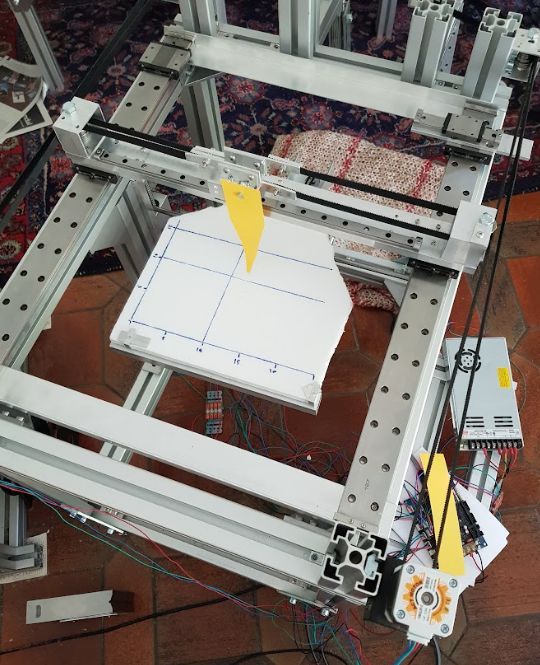
Aluminium 45x45, F608 ball bearings, THK linear guides.
There are two carriages on the THK linear guide each. I'll use the second for a router solution for abrasive work.The reason to build it is to
- verify the robot kinematics firmware
- give examples how to configure, home and print
- discuss problems with optional recreation
The A and C axis are belt gear based:
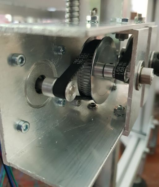
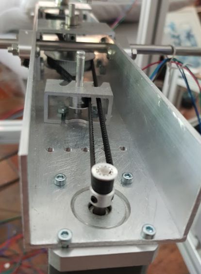
The C axis has long belts and long distance between A and C axis intentionally to check the firmware correctness. It will be better for productive use that the C axis is above the A axis with a counterweight (eg stepper) below it, so it's balanced to avoid falling down when steppers power off.
The belt gears are 12/60 teeth in two stages each, so 1:25 each.
To calculate the distances of the gear axes, I used https://www.technobotsonline.com/timing-pulley-distance-between-centres-calculator.htmlThe C axis with 8 mm steel rod is too weak, it bends too much for my taste, I'll have to use an alternative or support it.
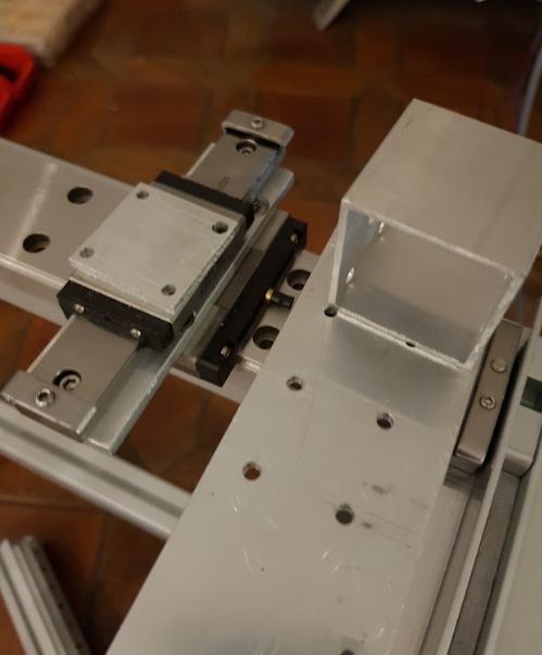
The X axis has a linear guide below it. In my current understand, thermal expansion is not the main problem why it's necessary, but one cannot calibrate the two rails exact enough (few micrometers necessary in all planes), so they would stuck fast:
The clamps for the XY belts were complicated, there are always screws in the way! I'll use Mark's belt clamp probably in the future:
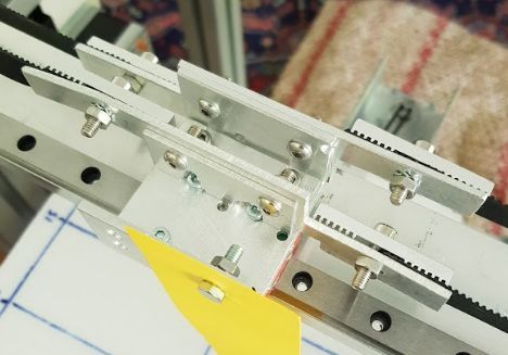
XY belt tensioner is using linear guides and weights. I can fix the position by the clamp. It's good to have a protection against wire tear:
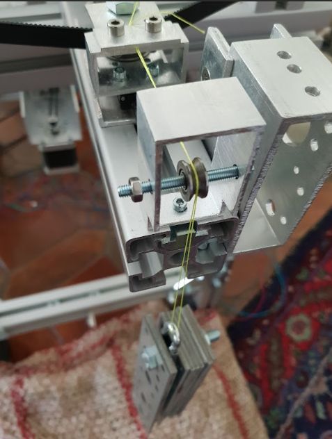
The weights can be changed to calibrate XY. Better than those steel weights would be something like high density gold bars, but I didn't have them on hand. The wire is fishing line 40 lbs. I will probably use this construction to use weights for other tasks too, where I need a defined force.
The "print bed" is polystyrol and a paper hotend to avoid damage while testing:
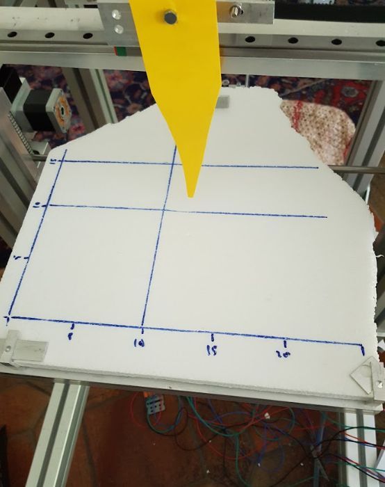
Some first test results are:
- when A axis is rotating, there are crashed with the frame which are unexpected. To build in collision detection may be a good idea
- same with A rotating and RTCP XYZ compensation means that eg Z remains at its position, but the motorPos not! A configuration of motorPos range may be necessary to avoid the crash.
I used 2 steppers for Z axis:
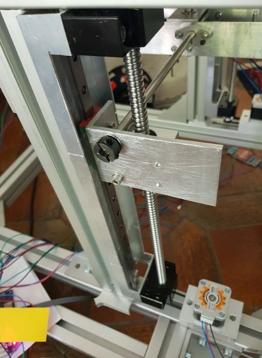
The reason is, I tried the belt solution to connect the two axes, but the belts are in the way of the rotating A axis. Routing the belts around the area was a complex task. The second reason is, the two steppers for Z will allow a small tilting (at AC, this means a third rotating axis around B), this may be useful in the future for slerp 6 axis based (Yan, Jeng, Chieng Five-Axis Slerp for Tool-Orientation...).
To test different Duet boards, I used Wago connectors:
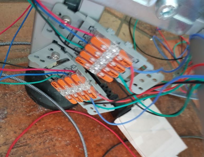
Crimping was again my "favorite task".
I search a solution to allow free rotation of the table. I'll probably design something similar to "RS Pro 176-0897" for the bed heater.
That's for the moment. I am currently testing my setup and will describe it later, same as my thoughts about homing and then trying FullControl for sample prints.
I'll make new bins this evening with my firmware corrections for Mini5, 6HC and Duet2.
One hint at the end: set stepper speeds low while testing, so you have enough time to press the emergency stop button...
-
The next prototype will be a CNC 5 axis, and now may be a good moment to share my experience with manual tools, so I gathered some ideas:
one of the most valuable tools I have is this one, together with a good caliper:
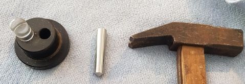
which allows more exact graining(my model: Soba Optical Center Punch).
The next hint is to measure bought parts, there are surprises sometimes:
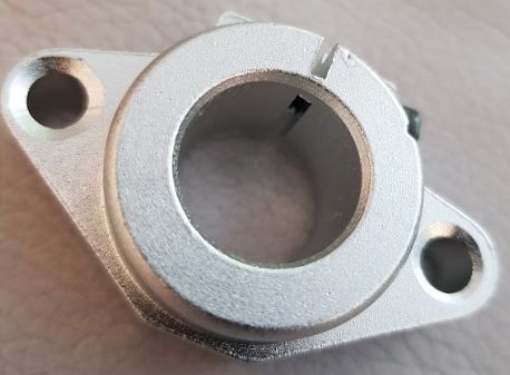
and sometimes a part which has a documented thickness of 31.5 mm has only 30.0. Aluminium extrusions are not flat in most cases. There's a reason why CNC people route them before using. Your construction should not rely on extrusion's flatness (if you have not routed it):
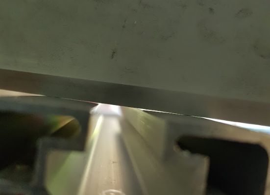
using a hair angle or hair lineal, great tools to check flatness.
An aluminium part is not necessarily 20 mm, but sometimes 20.2, and not 2 thick, but 2.15. Measuring deepness of the carriage holes is also a good idea (all holes), because they differ, to choose the right screws.
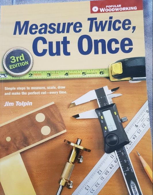
Talking about measuring, this is one of my favorite book titles:
I bought some waste aluminium for 3 EUR/kg, and my next hint is to practice a lot, using the failed attempts for washers and the like. After graining, boring etc many parts you have gained experience. Then it becomes quite easy to make a part.
One very useful tool is a band saw, I use a Proxxon MBS220, which is enough to saw 6 mm alu. But be careful, the parts become hot after sawing, especially with big drills like a drill to bore 16 mm holes (use coolant like cutting oil).
I try to achieve stable structures by using aluminium 3 mm or thicker, creating closed objects. I always try to use two connections to hold parts or shafts by ball bearings to hinder rotation or tilting.
A special topic is deburring, which I often do between single holes, because they level the parts wrong when not doing it (the next hole is not vertical any more). Burrs look ugly, but more important, they prevent good connections or alignment. For high precision, I use cone drills for final processing of a hole.
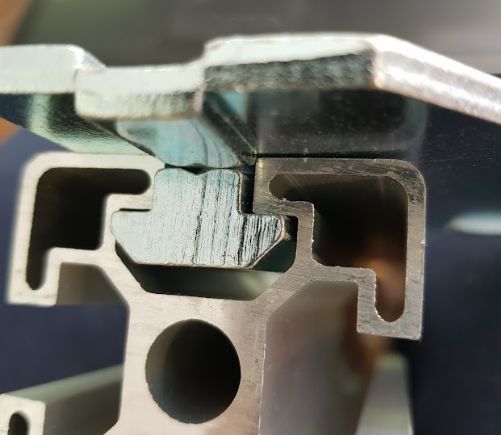
I prefer nut stones with spring, because they can be inserted without disassembly of the frame. Hammer stones alway rotate into the wrong direction, but sometimes they are needed because they need less space.
An example of a failed nutstone usage is here, where the angle recess conflicts with the nutstone height. The connection is very loose as result:
When designing parts, holes to access screws (eg the pulley screws) is important. At the same time I try to make closed structures for stability.
The carriages of the linear guides need to be protected against moving over the guide edges. I you already searched the balls, you know what I mean. Even worse for ballscrew.
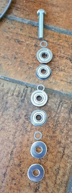
For rotating parts, I often insert washers. This special 8x12x0.5 washers between the F608 make the connection only at the inner (not rotating) part, not the outer, so the F608 can rotate without friction:
Talking of washers, the old locking washers DIN 127A, 127B, left were withdrawn because they are unreliable:

I use the right one DIN 6797 Form A, but there are many options with different capabilities like DIN 6797 form J, 6798 multiple forms, 7980 etc. I choose 6797 because they shall protect against vibrations.
-
I've installed a new longer (18 cm) hotend for less crashs (see below)
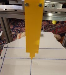
and created new binaries and checked in the current code. I rewrote the RTCP code and tested it. This builds have all limits like M208, angle and speed limits deactivated.
To give an impression, my current configuration part for setting robotic is:
M669 K13 B"CoreXY5AC"

M669 A"C=-179:179:0"
M669 A"A=-179:179:0"
M669 A"Z=0:300:0"
M669 A"X=-150:150:0"
M669 A"Y=-150:150:0"

M669 C"C=0:0:1:0:0:0"
M669 C"A=1:0:0:0:140:-70"
M669 C"Z=0:0:1:0:0:0"
M669 C"X=1:0:0:0:0:0"
M669 C"Y=0:1:0:0:0:0"

M669 C"Mnoap=1:0:0:0:1:0:0:0:1:0:0:0"
M669 C"Mreference=0:0:0:0:0"

G92 X0 Y0 Z0 A0 C0
The most important is the Mnoap endpoint. If I home all 0 values to this endpoint, calibration is easiest. A good endpoint is the middle of the bed, on the Z0 surface of it. This is cartesian coordinate (0,0,0) also. The axis points are next important and the need to measure them more exactly is an open task.
BTW I really don't understand why Z is axis orientation (0,0,1), because the positive Z should point down. Another point is that the Voron is opposite direction of traditional CoreXY: Voron platform down means less distance hotend-endpoint. Traditional bed up means less distance. So Z axis orientation may need to be opposite for Vorons.
With G92 I set homing for all axes, and the M114 Count values are 0 each because the endpoint is 0. Controlling motor and machine positions is easier.
RTCP seems to work ok, only C has some inexactnesses. But I suspect this is the missing exact calibration. A, X, Y and Z move nicely RTCP according to the AC rotation. One open issue is at X0Y0, where the rotation by C is undefined for the inverse kinematics. I currently set rotation to 0, but the new C angle is stored.
The tool length parameters are removed, because it's only necessary to change the endpoint when changing tools. This is imho safer than trying to detect a tool change.
I've moved the bed deeper, because by testing A rotation, I constantly crashed the Z axis at the top. A terrible noise. Talking of A, I have to fasten the pulleys better, they were loose after a few hours. I'll connect the pulleys by screws and make notches into some shafts.
I added a reporting of the current configuration. When M669 is called (after setting robotic K13), it is output to the console, e.g.:
=== M669 K13 current config ===
numOfAxes 5 axisTypes RRPPP chain CAZ_corexy(XY) (normal CAZ.. special XY)
axis C ori: 0.00 0.00 1.00 point: 50.00 -50.00 0.00 angles min/max/home: -179.00 179.00 0.00
axis A ori: 1.00 0.00 0.00 point: 0.00 120.00 -75.00 angles min/max/home: -179.00 179.00 0.00
axis Z ori: 0.00 0.00 1.00 point: 0.00 0.00 0.00 angles min/max/home: 0.00 300.00 0.00
axis X ori: 1.00 0.00 0.00 point: 0.00 0.00 0.00 angles min/max/home: -150.00 150.00 0.00
axis Y ori: 0.00 1.00 0.00 point: 0.00 0.00 0.00 angles min/max/home: -150.00 150.00 0.00
Screw values:
   reference angles/positions:  0.00 0.00 0.00 0.00 0.00
   endpoint axis X: 1.00 0.00 0.00
   endpoint axis Y: 0.00 1.00 0.00
   endpoint axis Z: 0.00 0.00 1.00
   endpoint point: 0.00 0.00 0.00
special kinematics set: CoreXY
abSign: 0  (0 means A (B) positive angle preference)
cache used: 80 maximum: 200
I'll add a summary check for completeness.
-
About Calibration:
the X, Y and A axes shall be horizontal and parallel to each other in the XY plane. I use this tool to calibrate it:
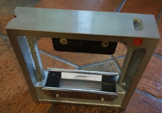
It has precision of 0.02 mm/m, but of course every spirit level will do. Or dial gauge constructions for more precision.
When the bed 0,0 is on the position of the C axis, the is no C offset to measure, so
M669 C"C=0:0:1:0:0:0"
The first three parameters are the axis orientation, the next three the offsets. Orientation is to the Z top, i. e. looking from above, positive angles are counterclockwise.
If there is an offset between bed 0,0 and the C axis, the X and Y offsets are to be measured. The Z offset can be set to any value (the rule is to set to any point on the axis).The offsets of the A axis are to be measured:
offset Y:
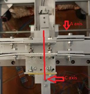
If C axis and bed origin have XY offsets, the Y offset between bed and A axis needs to be measured instead.
offset Z:
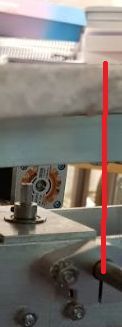
which means to measure including the bed thickness.In my case:
M669 C"A=1:0:0:0:140:-70"
If the A axis is below the bed, Z is negative.
The X offset is irrelevant, because any point on the axis can be taken.That's all about axis measuring, because the axis positions of the linear axes don't play a role for the calculation. It's only important where in respect to the rotary axes they are placed (this is specified with the B parameter).
The final task is to home the axes, so the reference coordinates match the endpoint position. Or other round, place the endpoint perpendicular to the center of the bed and set homing values of the 5 axes to 0 each. I'll describe how I try to home most exactly in one of the next posts and which options there are.
-
Short update of the build 28 July:
for A0 the inverse kinematics didn't rotate C, because for the vertical Z axis there is no C solution. To make it short, I've implemented a solution around so C rotates. The advantage is, A0 can be used to have a hotend which follows the print path.
When A changes between positive and negative, there are sometimes very rude and fast C rotations by 180 degrees. I've added abSign=2 which doesn't correct C degrees. Need more testing and validating.
Another experience is that precision is key, I'll make the construction stiffer at the weekend. I have often crashes at the frame, so all calibration is gone. The Z is quite limited by the RTCP corrections.
The next is Z axis, based on ballscrew. I was becoming aware that when the table rotates by AC, the Z axis becomes the new XY axis (from the viewpoint of the print object), so the speed is too low. There are three options:
- place the Z axis to the bed like "traditional"
- place the Z axis to the XY frame like Voron
- place the Z axis to the hotend like a gantry CNC does it
The first two options have high mass to move, so I'll try the third option next, probably belt based. This options has the same Z movement as Voron (moving Z when Z axis points down diminishes the distance hotend-bed), so it's a test for Voron as well.
-
@JoergS5 said in JoergS5's CoreXY 5 axis (robot kinematics):
A0 can be used to have a hotend which follows the print path.
That would be handy for air-assisted laser or baird-air print cooling:
You could aim the air, where it is most effective.place the Z axis to the hotend like a gantry CNC does it
Then you need a very stable joint between the real XY-gantry and the z-axis. It would be best to have two XY-rails and two z-rails building a #.
-
@JoergS5 have you looked at the zeroing solution the BrendonBuilds implemented for the Voronoi build:
https://github.com/FreddieHong19/Open5x/tree/main/3D_Model/Voron_0/DuetConfig/macros
This is interesting because it relies entirely on Meta Gcode to set the 0,0,0,0,0 position of the 5axis machine.
Currently it simply iterates through to the 0 crossing point one axis at a time, this may be sped up using a different method to iteratively determine the 0 point. It relies on a nozzle touch probe which on the Voronoi is implemented with electrical contact.
-
@T3P3Tony thank you for the link. I'm thinking a lot about how to home and calibrate fast, e.g. with the help of the LDC1612.
-
@o_lampe I currently plan to use two linear rails for the X axis (one in front, one on top) to stabilize the Z axis vertically. This will be especially important for a long Z.
-
@JoergS5 yes, we have also discussed this. Using the LDC1612 to detect the nozzle.
-
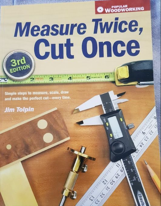
3rd edition? You'd think they would have got it right the first time.

-
-
@Phaedrux also that tape measure looks wrong...
-
This post is deleted! -
I've change the kinematics from screw theory to geometric algebra. It works much better now, especially with the Z direction, I had some errors.
Screw theory says that directions of axes must be reversed, depending on whether the axis is attached to the hotend or the table. I'm unsure whether it's the same with geometric algebra. This matters for Voron, whose Z axis is attached to the hotend part. If it matters, I'll have to add a paramter to specifify whether X, Y, Z axes are attached to hotend or bed.
I expected that geometric algebra is slower than screw theory, but to my surprise it is faster: 15 microseconds (for both forward and inverse) compared to 30 of screw theory for each segment calculation. M669 R gives a statistic. (M669 R currently unhomes all axes, I don't know why).
=> Edit: I know why it unhomed, it was the seen variable in Config. I've added a D parameter (see documentation on the main page) to decide not to unhome if wished, if configuration is changed.
I currently build bins and will upload to github together with the sources. Duet 2 still compiles without error.
BC mode should work also, but I have no BC prototype and cannot test it.
I saw an article to build a machine with two rotary axes with arbitrary angles, this I will investigate. It uses Paden-Kahan 2 to translate AC/BC angles into the machine angles. This will cost processing time however.
-
Short update about my activities:
I am aware that RRF is restricted by memory and performance. It has only a few KB or available RAM and every ms is important. So I thought about how to optimize the usage for robot kinematics and will try the following procedure:
- best performance is when the axes are perpendicular and AC/BC axes are in A/B/C directions. The calculation is easiest then and performance best
- the algorithms allow skew axes and arbitrary axes also, so I want to support them also
- so I'll establish a decision tree to use the simple, fast calculations when configuration uses the first case and full calculation for the other
- at every move, first is a call to LimitPosition, so I can check configuration changes there and cache values if possible
- one performance measure I didn't use yet is to cache AC/BC values for moves where AC/BC don't change. I'll implement this now
For memory usage of the bin file, I'll remove every code which is not used. I have a lot of code to calculate between transformation matrix, quaternions, Euler angles, CGA and skrew theory. I don't want to loose it, but storing it into RRF uses much memory. So I'll make a separate github project to store it there. The redundant solutions allow cross check of the calcuations.
For visualisation, the DWC is a bit problematic for me, as I don't want to migrate between C++ and TrueScript. I'll use C++ with OpenCV until I have a better solution (or someone can tell be a solution). So I can use one C++ code base.
An open topic with 5 axis is that rotations are not velocity constant. I'm thinking about how segmentation could be changed, but this is code outside kinematics, it is part of the core RRF. An intersting article to introduce into the topic and how it could be solved with a modified slerp is "Yan/Jeng/Chieng Five-Axis Slerp for Tool-Orientation Planning in a Five-Axis CNC Machine".
-
@JoergS5 I am very interested in your progress so far. I am about to build a mini mill and will at some stage get a 4th and 5th axis so if you need help testing let me know. I will most definitely be 3-4 months off getting it done as funds don’t allow it at the moment so the project is being drip fed
-
@samlogan87 my next step is to CNC including milling, so my activities will help your project. I have e.g. a boring head (german: Ausdrehkopf) which I want to integrate.
-
@JoergS5 said in JoergS5's CoreXY 5 axis (robot kinematics):
Voron, whose Z axis is attached to the hotend part
Just a note. this is only the case for Voron 2.x, V0 and Trident move the bed.
-
@T3P3Tony thank you Tony for the comment. It's important to be aware where the axes are attached (hotend or bed), because this reverses the calculation.
I'll make a decision matrix in the documentation with sample config settings to make it clear. Especially with CNC and milling there are several variants, e.g. the A axis being at the drill side.
