Scanning Z probe support in RRF 3.5
-
@JoergS5 my feeling at the moment is that because of the sensitivity of inductive sensors to temperature, and to allow a wider choice of bed surfaces including interchangeable beds, it's better to use a conventional touch probe or nozzle contact probe to establish Z=0 and perhaps to do bed tramming too. Then the scanning probe can be calibrated immediately before scanning, and its temperature sensitivity won't matter.
As you can see from the pictures at https://coolcomponents.co.uk/products/grove-2-channel-inductive-sensor-ldc1612 there is a blank area in the centre of the coil, so drilling a hole there would be possible.
We're designing a solution based on the LDC1612 at present and although we will be using a smaller sense coil than the Grove one, it's likely that we will include a hole in the centre and design a printable adapter to attach it to a BLTouch.
-
@dc42 said in Scanning Z probe support in RRF 3.5:
We're designing a solution based on the LDC1612 at present and although we will be using a smaller sense coil than the Grove one, it's likely that we will include a hole in the centre and design a printable adapter to attach it to a BLTouch.
@dc42 Wouldn't the inductive probe pick up the metal in the bltouch? I've assumed this was basically a small metal detector hence you'd need to keep any other metal outside of the coils sense area, or is that not the case?
-
@CNCModeller a small amount of metal in a fixed location relative to the coil shouldn't matter. In any case, the larger metal parts of the BLTouch are at the top so about 26mm away for where the coil would be.
-
-
@CNCModeller I am using the probe with a flexible magnetic sheet. I was expecting the magnets underneath it to show up in the height map, but they don't. However, the instructions for the Beacon probe say you need to avoid strong magnets.
-
@dc42 said in Scanning Z probe support in RRF 3.5:
@CNCModeller I am using the probe with a flexible magnetic sheet. I was expecting the magnets underneath it to show up in the height map, but they don't. However, the instructions for the Beacon probe say you need to avoid strong magnets.
@dc42 In your experience, does the height map reference to the magnetic sheet surface or the underlying metal bed?
-
@CNCModeller I can's say because I don't use one without the other. However, the fact that the probe doesn't see the magnets suggests to me that it is sensing the sheet.
For reference I am using this bed https://mandalaroseworks.com/products/magbed-for-e3d-toolchanger and this sheet https://whambam3d.com/collections/build-surfaces/products/flexi-plate-with-pre-installed-pex-build-surface?variant=39372386566242.
-
@dc42 I'm using the type that looks like flexible rubber fridge magnets so we'll see how that compares. The flux is in long lines spaced at about 10mm pitch.
-
That mandalaroseworks bed does have pretty darn strong magnets in it!
@dc42 why not do a bed scan without the flex sheet installed just for comparison.
-
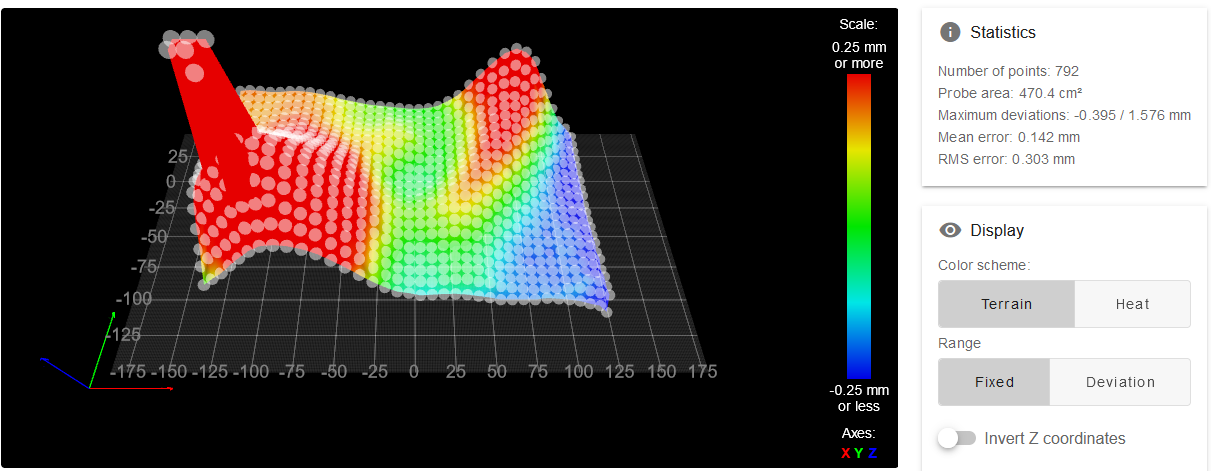
@T3P3Tony OK, here it is.
-
@dc42 cool, you can clearly see the magnets!
One other interesting test would be to put a thin shim in the middle under the flexi build plate (say a couple of M4 washers and see how accurately it picks up the deformation of the flex plate.
-
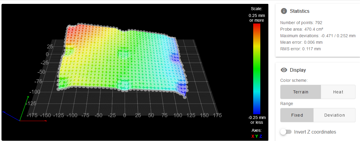
Here's the scan with the bed plate, for comparison. It looks to me that the magnets are being picked up very slightly.
-
-
@dc42 definitively confirms its picking up the flex plate and not the underlying bed/magnets
-

This is what the field lines on the magnetic build plate I'm using looks like, zoom into the magnetic detection film.
It's stuck to a 4mm thick mirror on top of a 4mm thick aluminium plate which has the 250v heater pad on the back of it.
It'll be interesting to see if the AC bed makes a difference when it's on. I guess I should be able to turn it off for the scan once the bed is up to temperature.
I'm assuming the inductive probe will pick up on the mirror coating if it doesn't interact with the rubberised magnetic build sheet.
It'll be a while before I can test this as I've got a lot on at the moment but everything is in hand to give it a try.
For the record very impressed on how quickly this has been done, as always the Duet3D team is top banana


All the best
Barry M -
@dc42 These stronger magnetic sheets have alternating magnet orientation. (just mentioning it, not everyone knows)
It probably depends if you scan along the magnet lines or cross them. -
... and even when in line with the field lines the pitch of the scan might need to be the same as or multiples of the pitch of the field lines. And that assumes every field line is the same strength.
Will be an interesting experiment none the less...
-
@CNCModeller I don't think the static magnetic field should affect the sensor significantly, because it's unlikely to cause magnetic saturation.
-
I've made some further improvements to the scanning probe software:
- Previously I was fitting the sensor frequency vs. height calibration points to a quadratic curve. When I plotted the residual in a spreadsheet I saw that there was a small cubic residual error. Now I fit a cubic curve to the points instead.
- I hadn't noticed that during calibration, when the sensor got close to the bed it returned an amplitude error, which affected the calibration. I have increased the oscillation amplitude to fix this.
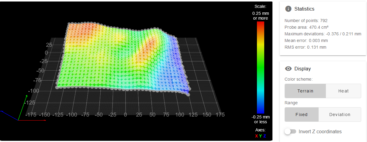
Here is a 522 point height map produced by the scanning sensor in 21 seconds, including the time taken to do a regular probe at bed centre (to establish an accurate Z=0 datum) and then calibrate the scanning probe:
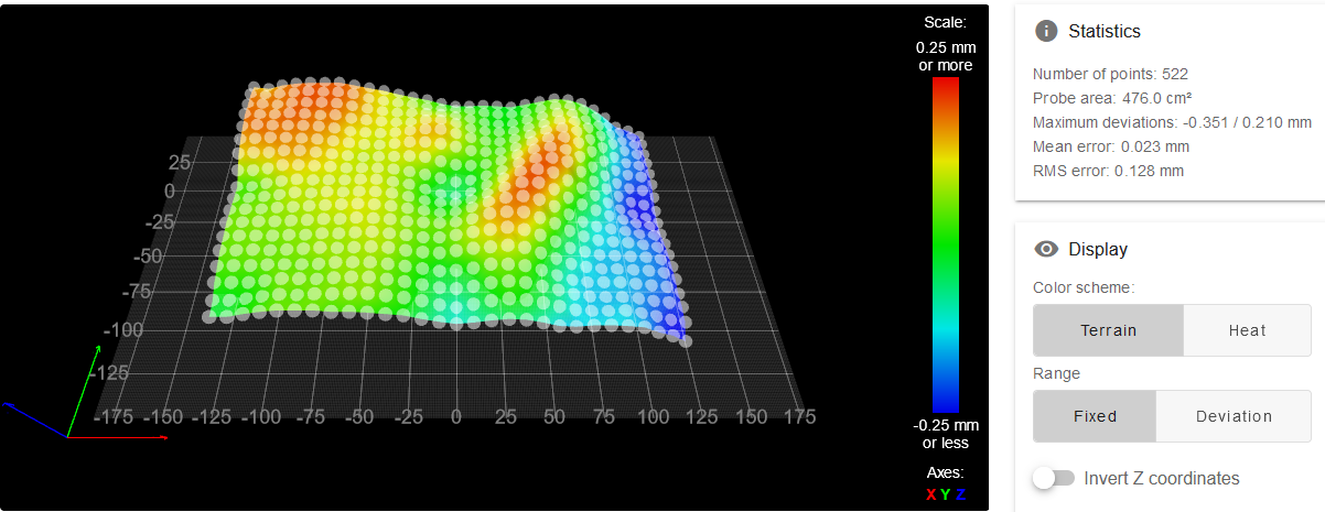
Here is a height map of the same bed produced using the microswitch probe in 5 min 28 seconds (I reduced the dive height to 2mm to speed up probing):
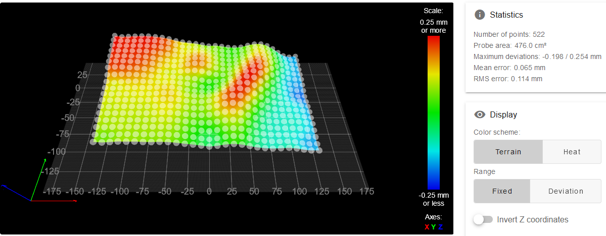
There's not much difference between them, except for a 0.04mm offset that I need to track down.
-
@dc42 when you did that, was the bed warm or are you still playing around with it when it’s cold?
