Large scale toolchanger, Z-stop as toolhead sensor
-
My first post here!
I've been searching for this topic for quite a while without any results so I figured asking the almighty Duet gods would do the trick

I am currently testing a custom built large scale toolchanger with two toolheads, and as a safety feature I would like to use the Z-stop as a trigger to confirm whether a tool is mounted to the effector or not.
I am using a Duet 3 MB6HC, with RRF 3.4.5.
The printer itself works great, however a recent incident where the x and y axis skipped a few steps resulted in a lot of extrusion for both tools while docked (motor stall detection will also be configured)

The printer is a corexy and the bed is stationary, so the effector/tool is moved in XYZ.
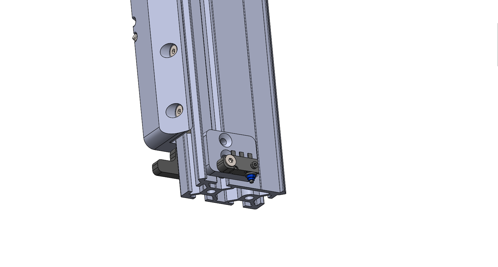
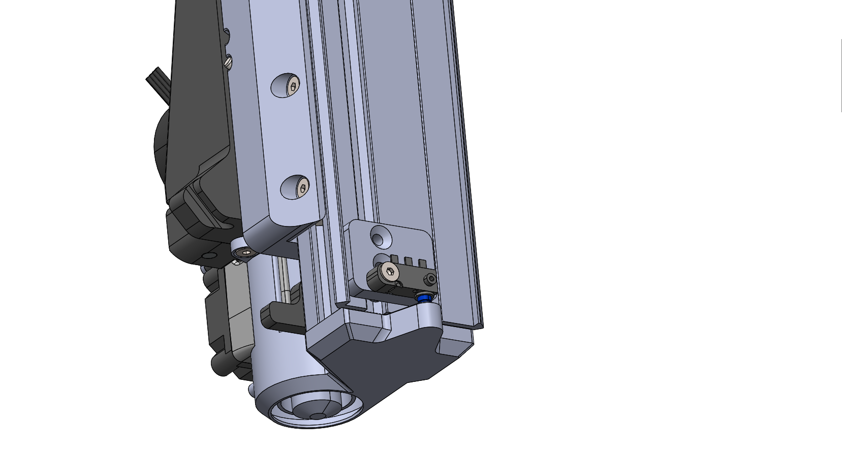
The Z-stop is the same type microswitch as on the e3d-toolchanger (D2HW-C201H), and probing of the bed is done when both tools are parked. When a tool is connected a tab on the toolhead presses the Z-stop.
Effector seen from the rear with no tool:

Effector seen from the rear with tool:

Here is how the Z-stop/Z-probe is configured in config.g
; Endstops
M574 X2 S1 P"io8.in"                                       ; configure switch-type (e.g. microswitch) endstop for high end on X via pin io8.in
M574 Y2 S1 P"io1.in"                                       ; configure switch-type (e.g. microswitch) endstop for high end on Y via pin io1.in
M574 Z1 S2 P"io6.in"                                       ; configure switch-type (e.g. microswitch) endstop for low end on Z via pin io6.in

; Z-Probe
M558 P8 C"io6.in" H2 F500:100 I0 T100000                   ; set Z probe type to switch and the dive height + speeds
G31 P200 X0 Y54.15 Z-9.83                                  ; set Z probe trigger value, offset and trigger height (Z-9.63)
M557 X12.5:453.5 Y55:885 P5:10                             ; define mesh grid
What I am hoping to achieve is something like this:
-
At start of print, use Z-probe to do mesh bed probing
-
When selecting tool;
Check that switch is not triggered before tool is mounted
Check that switch is triggered after tool is mounted -
During printing;
Check that switch is triggered, if not run trigger#.g -
When deselecting tool;
Check that switch is triggered before parking tool
Check that switch is not triggered after tool is parked
Any ideas on how to solve this?

Full config.g:
; General preferences M552 S1 ; turn network on M575 P1 S1 B57600 ; enable support for PanelDue G90 ; send absolute coordinates... M83 ; ...but relative extruder moves M550 P"3D'LitePrinter" ; set printer name M669 K1 ; switch to CoreXY mode ; Calibration Califlower 3D'Lite 2.xlsx M556 S100 X-0.375 ; Axis skew compensation ; Network M552 P0.0.0.0 S1 ; enable network and acquire dynamic address via DHCP M586 P0 S1 ; enable HTTP M586 P1 S0 ; disable FTP M586 P2 S0 ; disable Telnet ; Drives M569 P0.0 S0 ; physical drive 0.0 goes backwards M569 P0.1 S0 ; physical drive 0.1 goes backwards M569 P0.2 S1 ; physical drive 0.2 goes forwards M569 P0.3 S1 ; physical drive 0.3 goes forwards M569 P0.4 S1 ; physical drive 0.4 goes forwards M584 X0.1 Y0.0 Z0.2 E0.3:0.4 ; set drive mapping M350 X16 Y16 Z16 E16:16 I1 ; configure microstepping with interpolation M92 X159.70 Y159.70 Z400.00 E548.00:548.00 ; set steps per mm (X/Y 160, calibrated, E400, calibrated) M566 X600.00 Y600.00 Z60.00 E2500.00:2500.00 ; set maximum instantaneous speed changes (mm/min) M203 X14000.00 Y14000.00 Z1000.00 E6000.00:6000.00 ; set maximum speeds (mm/min) M201 X1000.00 Y1000.00 Z500.00 E5000.00:5000.00 ; set accelerations (mm/s^2) M906 X1680 Y1680 Z1000 E850:850 I70 ; set motor currents (mA) and motor idle factor in per cent M84 S120 ; Set idle timeout ; Axis Limits M208 X-60 Y0 Z0 S1 ; set axis minima M208 X530 Y890 Z105 S0 ; set axis maxima ; Endstops M574 X2 S1 P"io8.in" ; configure switch-type (e.g. microswitch) endstop for high end on X via pin io8.in M574 Y2 S1 P"io1.in" ; configure switch-type (e.g. microswitch) endstop for high end on Y via pin io1.in M574 Z1 S2 P"io6.in" ; configure switch-type (e.g. microswitch) endstop for low end on Z via pin io6.in ; Z-Probe M558 P8 C"io6.in" H2 F500:100 I0 T100000 ; set Z probe type to switch and the dive height + speeds G31 P200 X0 Y54.15 Z-9.83 ; set Z probe trigger value, offset and trigger height (Z-9.63) M557 X12.5:453.5 Y55:885 P5:10 ; define mesh grid ;M376 H5 ; Hnnn Height (mm) over which to taper off the bed compensation ; Heaters M308 S0 P"temp0" Y"thermistor" T100000 B4138 ; configure sensor 0 as thermistor on pin temp0 M950 H0 C"out1" T0 ; create nozzle heater output on out1 and map it to sensor 0 M307 H0 B0 R5.671 C91.1:73.0 D1.36 S1.00 V23.8 ; disable bang-bang mode for heater 0, set PWM limit and PID tuning parameters M143 H0 S290 ; set temperature limit for heater 0 to 290C M308 S1 P"temp1" Y"thermistor" T100000 B4138 ; configure sensor 1 as thermistor on pin temp1 M950 H1 C"out2" T1 ; create nozzle heater output on out2 and map it to sensor 1 M307 H1 B0 R4.471 C118.4:92.2 D1.53 S1.00 V23.9 ; disable bang-bang mode for heater 1, set PWM limit and PID tuning parameters M143 H1 S290 ; set temperature limit for heater 1 to 290C ; Fans M950 F0 C"out4" Q500 ; create fan 0 on pin out4 and set its frequency M106 P0 S0 H-1 ; set fan 0 value. Thermostatic control is turned off M950 F1 C"out5" Q500 ; create fan 1 on pin out5 and set its frequency M106 P1 S1 H0 T45 ; set fan 1 value. Thermostatic control is turned on M950 F2 C"out6" Q500 ; create fan 2 on pin out6 and set its frequency M106 P2 S1 H1 T45 ; set fan 2 value. Thermostatic control is turned on ; Tools M563 P0 S"T0" D0 H0 F0 ; define tool 0 G10 P0 X0 Y0 Z0 ; set tool 0 axis offsets G10 P0 R0 S0 ; set initial tool 0 active and standby temperatures to 0C M563 P1 S"T1" D1 H1 F0 ; define tool 1 G10 P1 X0.2 Y0.3 Z0 ; set tool 1 axis offsets G10 P1 R0 S0 ; set initial tool 1 active and standby temperatures to 0C ; Filament sensors M591 D0 P3 C"io3.in" S1 R65:120 E5 A0 ; Magnetic rotating filament monitor connected to IO_3 M591 D1 P3 C"io4.in" S1 R65:120 E5 A0 ; Magnetic rotating filament monitor connected to IO_4 ; Miscellaneous M911 S10 R11 P"M913 X0 Y0 G91 M83 G1 Z3 E-5 F1000" ; set voltage thresholds and actions to run on power loss ; Accelerometer ;M955 P0 C"spi.cs3+spi.cs2" I50 ; all wires connected to temp DB connector, Y pointing upwards ; Input shaping M593 P"mzv" F25 ; Use MZV input shaping to cancel ringing at 25Hz -
-
You can't use the io6.in pin for both the probe and zstop at the same time, but you can unbind it and rebind it as needed before calling it into use.
If you sent M98 P"config.g" you'd probably see it complain about the pin being already in use.
To unbind the pin name to reuse it elsewhere you need to send the command again but with the pin name replaced by
nilC"name" Pin name(s) and optional inversion status, see Pin Names. Pin name "nil" frees up the pin. A leading '!' character inverts the input or output. A leading '^' character enables the pullup resistor1. The '^' and '!' characters may be placed in either order.
example
M574 Z1 S2 P"nil"
M558 C"nil"
So for the probing run, you'd need to unbind the pin and then send the M558 command with the io6 pin name.
Then after probing send the M558 command with nil to release it and bind it to the endstop with M574.
For 2 3 4 you can use conditional gcode in your tool change files to check things, or perhaps in daemon.g if you need to check state constantly.
Is that enough to get you started?
-
@AJ_Kodyna another option is to use conditional gcode in the tool change files to check the object model to see if the zprobe is triggered and then take appropriate action.
the object model key you need to look at is sensors.probes[0].value[0]