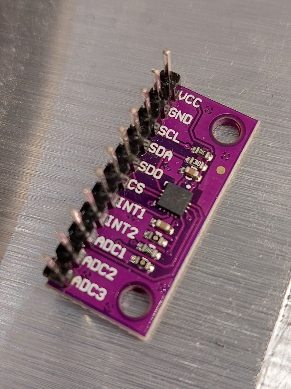
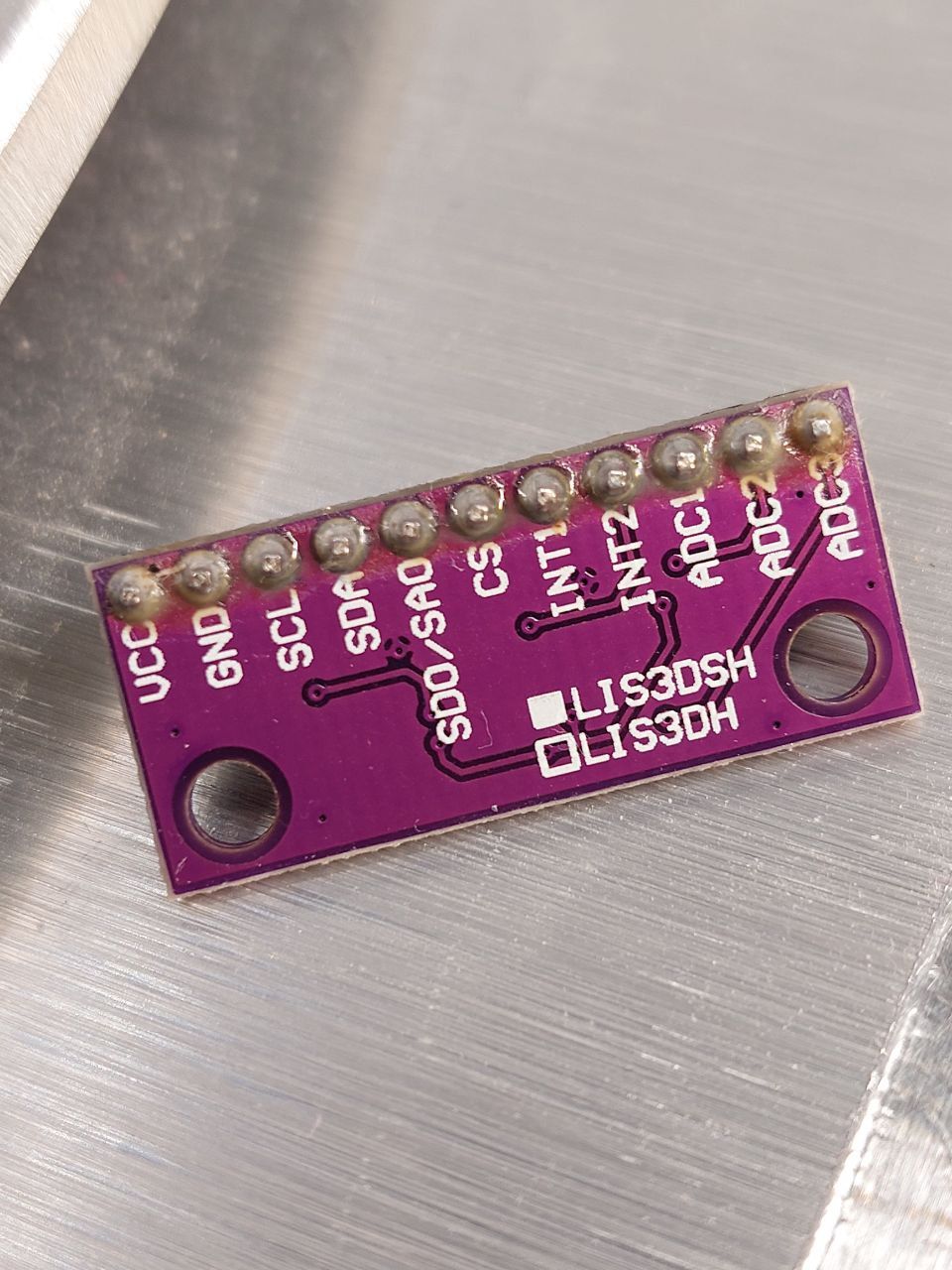
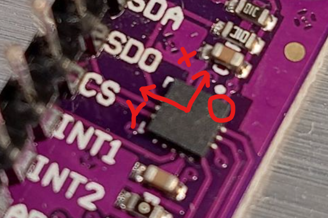
LIS3DSH orientation on a Delta printer
-
I had a look at the orientation guide by Nuramori: https://www.dropbox.com/s/hu2w5mk57l4zqpg/Accelerometer Orientation.pdf , but it didn't make much sense to me. I have a LIS3DSH, but it doesn't show X/Y direction. How am I to mount this correctly on a delta printer?
I can design and print an adapter to put on the duet smart effector, I just need to understand the correct orientation and M955 command.
For now at least. This is my first venture into accelerometers and input shaping, so might have more questions later.

-
@Velvia show photo of both sides of your accelerometer please
-
-
@Velvia better to take it from a bit further away and then cropping the photo so we can get a focussed view of the top side of the chip.
-
@oliof What information are you looking for? There are no X/Y/Z indications anywhere. It's not so out of focus that one cannot make that out.
-
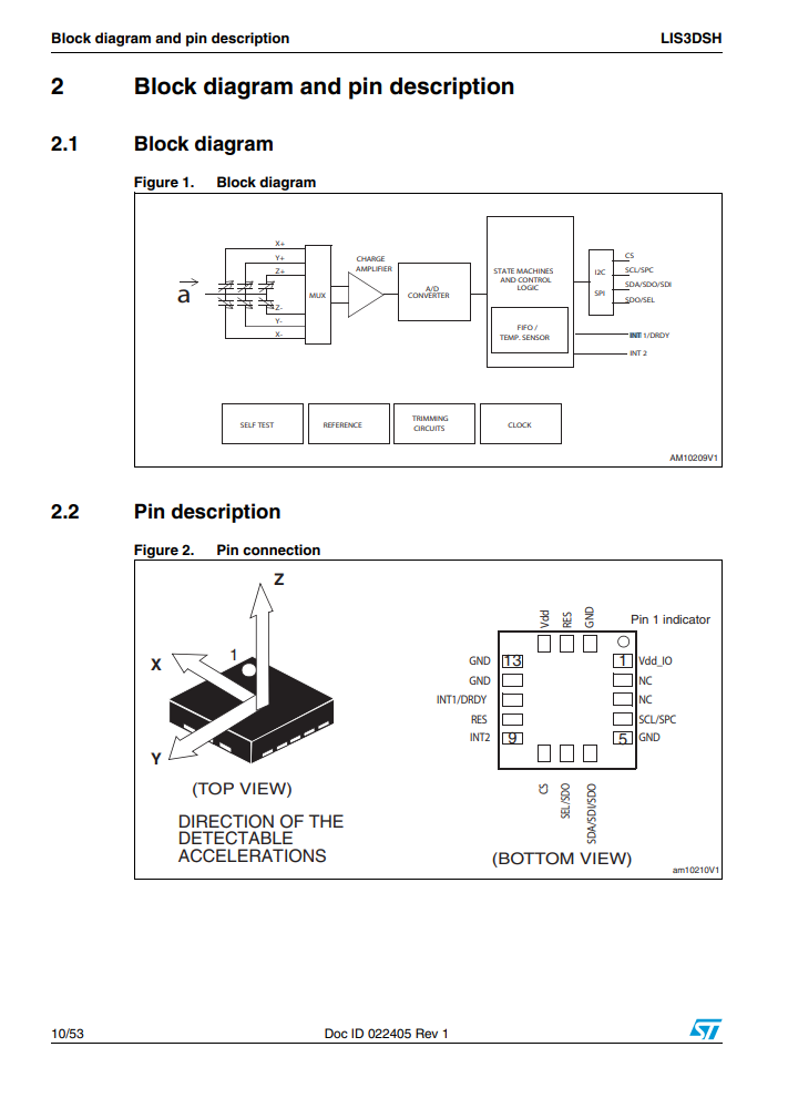
@Velvia I am looking for the Pin 1 indicator from your reference sheet
-
You can already see the chip has two sides with three legs, and two with 5. The bottom view says that the Pin 1 is VDD IO. Assuming Pin1 is where the white dot is on the PCB, Z is up the way the header pins point, Y is in the direction of the CS/DO pins and X is in the direction of the short edge where the VCC pin is.
For a delta, assuming the XYZ towers are like so
    Y


X        Z
I would mount the accelerator so that the pin headers are parallel with the front edge but oriented towards the Y tower
     Y
  ........
  |______|
X          Z
Then the axes of the accelerometer should match the coordinate system of the printer.
-
@oliof
I understand. It's barely visible, as tiny black hole. Was under the impression that it would be white.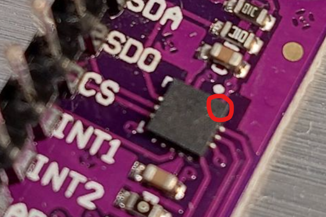
I guess they decided to mark it with the white dot above the chip, on the PCB instead.
-
-
Yes, I think you've annotated the photo correctly.
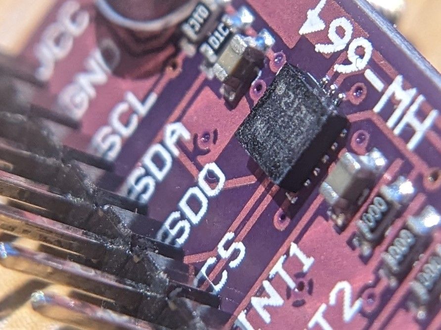
I have a board that looks very very similar to that, labelled LIS3DSH, advertised as a LIS3DSH, but actually I think it's a LIS3DH. The top of the chip on my board has clearly been abraded, presumably to try and conceal the markings.
I did some playing around with lighting and magnification and got as far as seeing the ghost of the markings, and the expected dot at the corner where the board has a dot. This photo has the markings a lot more visible than I can see with the naked eye:
-
I have now connected it, but the printer says it does not exists:
Error: M955: Accelerometer not found on specified portThis is how I have wired it:
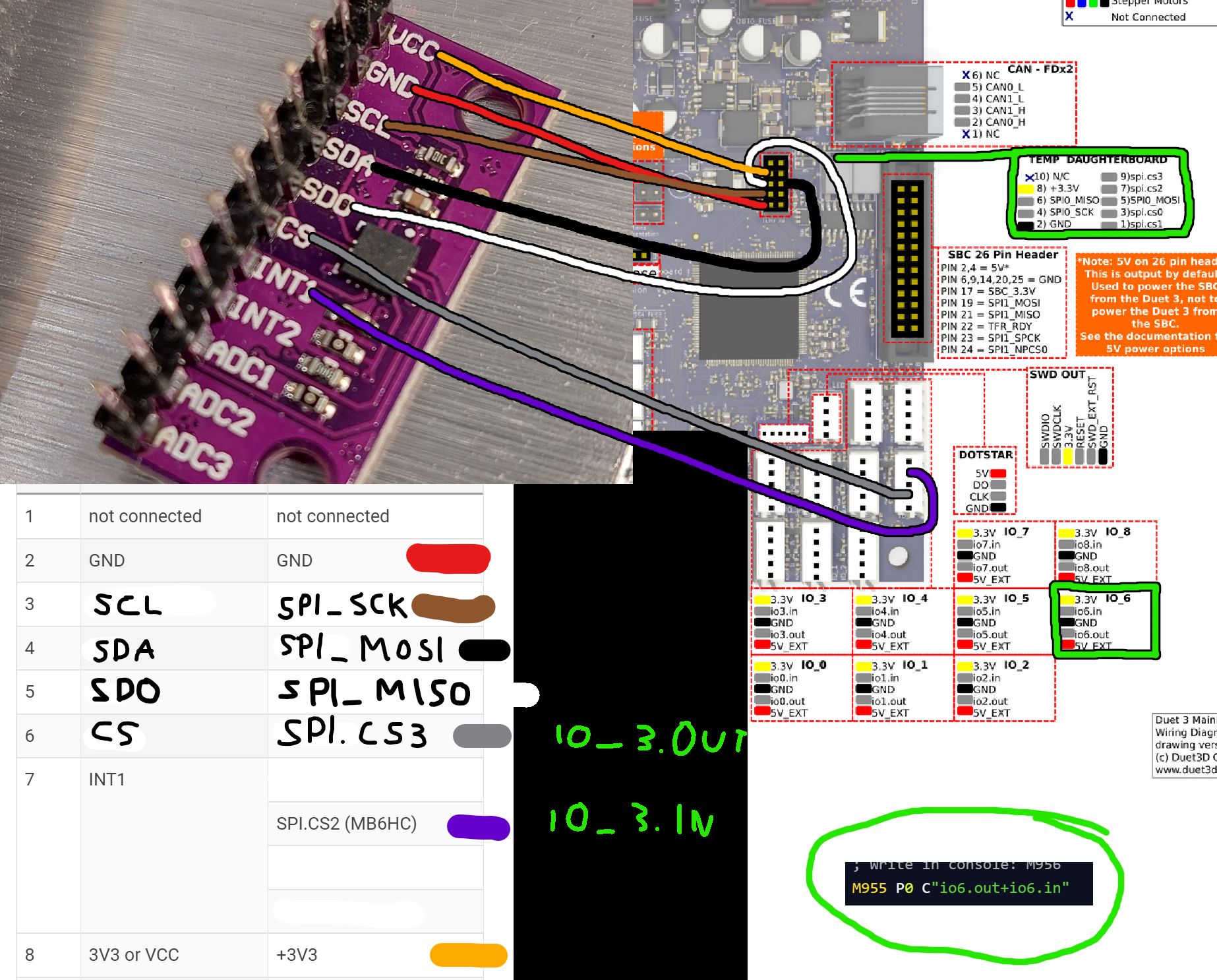
I put them on IO_6 instead of 3, since it was occupied. Any ideas?
-
@Velvia this is probably caused by the CS wire picking up noise from other wires. Here are some suggestions:
- Drive CS from one of the spi.cs pins on the daughter board connector, if one of them is free, because they have greater drive strength.
- Change the cabling so that the CS wire does not run close to any other wires except for Vcc and Gnd.
-
@dc42 You were right. It works now. Split the CS cable and ran it far away from everything else. Was able to make measurements now. Thanks!
Are there shielded ribbon cables available?
-
@Velvia said in LIS3DSH orientation on a Delta printer:
Are there shielded ribbon cables available?
Yes, however I have used unshielded ribbon cable successfully with these boards. If you use a 10-way ribbon cable and IDC connector to plug into the daughter board connector, then spi.cs1 can be used for CS because it is on the outside of the cable and the adjacent wire is ground.
-
I'm planning on using a shielded guitar wire for the cs wire when i wire mine up.
-
@dc42 I was able to get three readings, but now every time I try to get readings, it freezes the mainboard and it restarts.

-
@Velvia which firmware version are you using?
-
@dc42 3.4.1
-
-
@Phaedrux Thanks. I do that by running "M997 S0:1", right? Been a while
