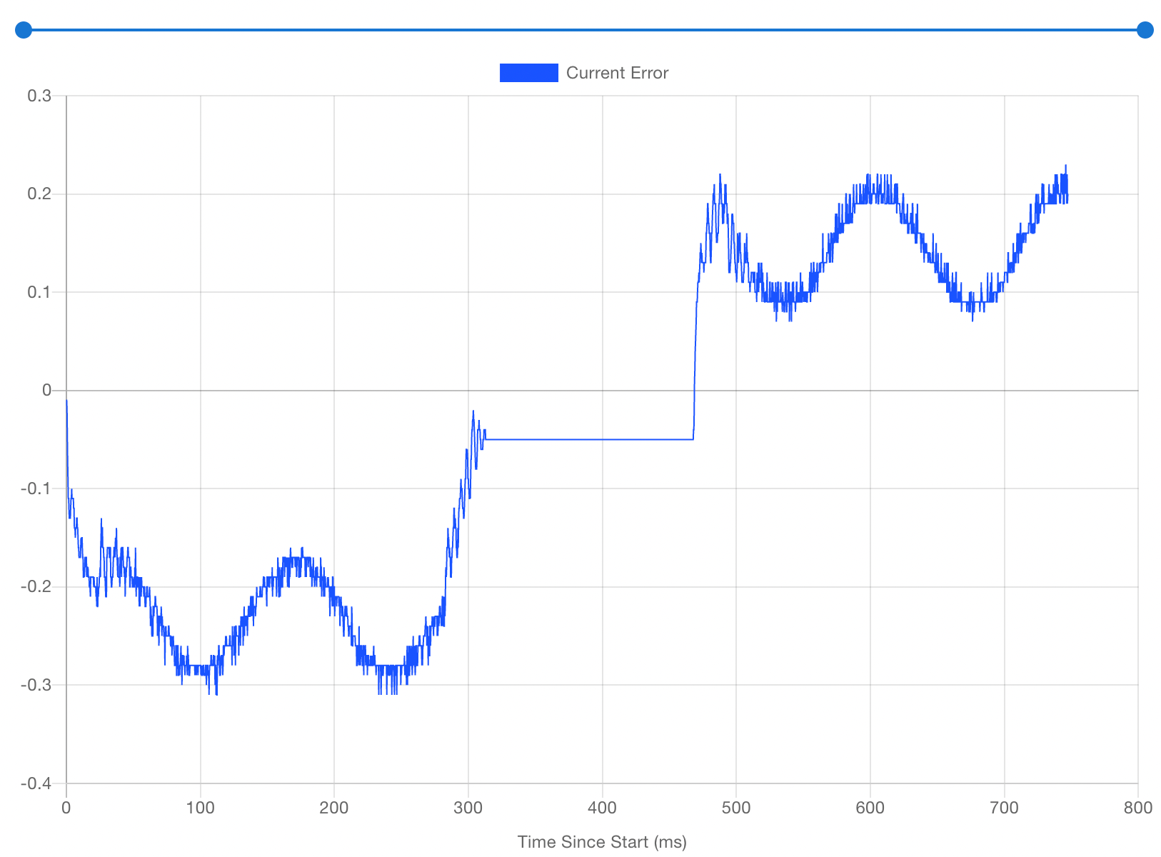
"Sawtooth" Error in Motion, Even Open Loop?
-
@evan38109
I'm only wild guessing here, but the 'unused' stepper isn't totally passive during the moves.
The FW tries to hold it in it's (microstep) position, which means both coils are pulling in both directions.
Maybe your encoders are so super sensitive, that they see this "fight"? -
What's the meaning of the error value? offset from expected position in degrees/percentage/microsteps/fullsteps?
-
The value "Current error" reported by the EXP1HCL is measured in full steps.
I suspect that what we are seeing here is that for most motors, the full steps are only guaranteed to be of the same size to within 5%, in other words there may be an error of +/- 0.05 full steps. Microsteps are even less uniform.
Also, the motor may not actually move at all on some microsteps because of friction, especially at low speeds. That may be the reason for the very fine oscillation superimposed on the sawtooth pattern.
-
@o_lampe With the belts removed from the steppers? Hmm...Nah, I think there's something else going on here...
-
@dc42 That makes sense. Candidly, one of the things I've been looking forward to seeing with the 1HCL was the actual accuracy of microstepping and open loop movement. And I think it's cool to see the lag during motion, which you'd expect from stepper mechanics.
But the error isn't +/- 0.05 steps, it's much bigger -- and it's not symmetrical.
Here's three rotations forwards and backwards, with a 100ms pause in between. Open loop, no belts attached. A couple things to note:
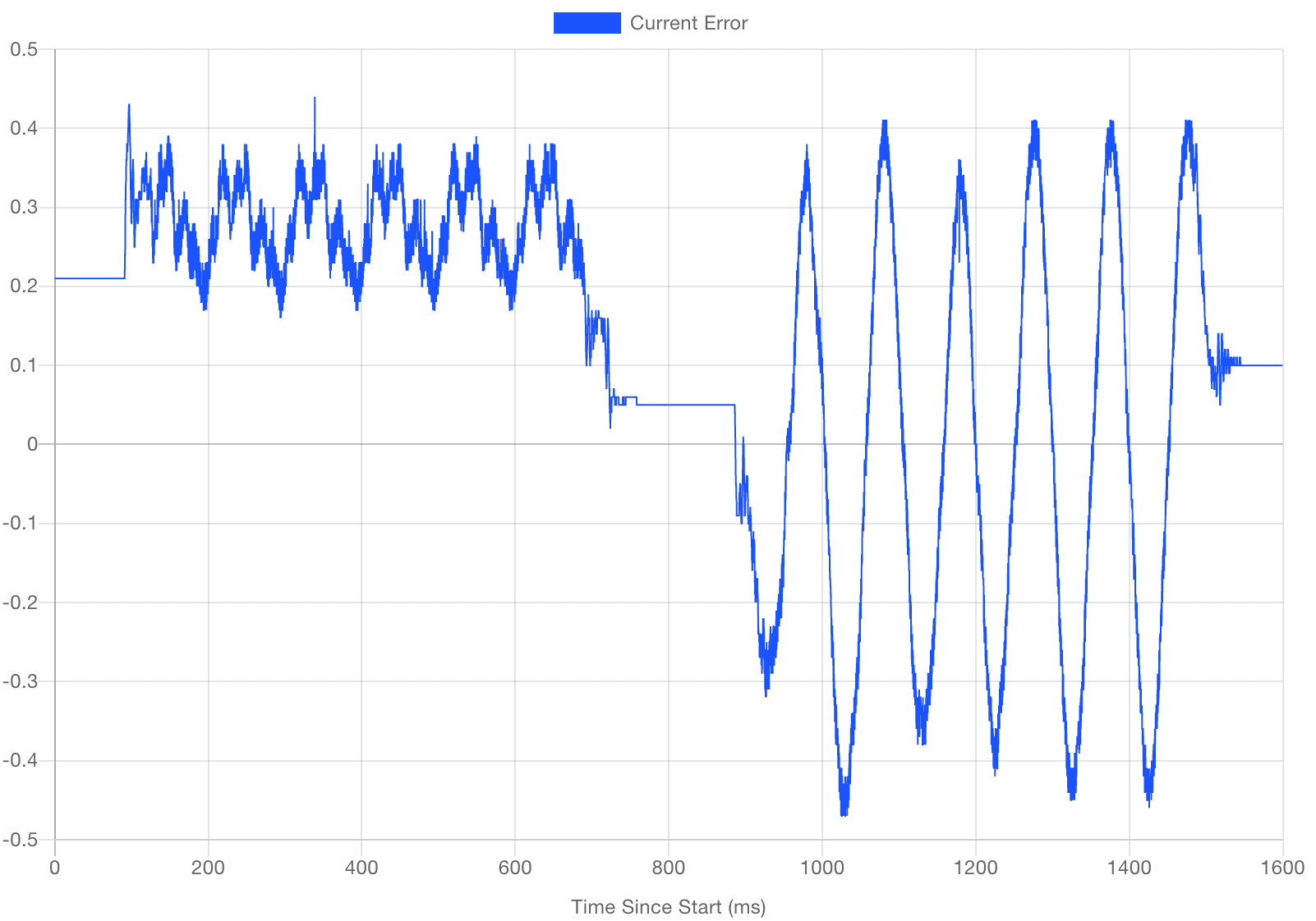
- The period of the oscillation seems to be half a rotation.
- There's a major asymmetry, which you see above as well.
The error is oscillating around 0.2 steps in one direction and up to a whopping 0.8 steps in the other. (Most times it's closer to 0.5 or 0.6, but sometimes...well, there's the screenshot...) You can see the same asymmetry in the plots from my first post as well.
It's making it just impossible to find decent PID settings.
Why would there be such an asymmetry in error depending on which direction a stepper is moving?
Edit: Oh, and if it makes a difference, here is the backlash measurement from encoder tuning:

-
@evan38109 thanks. The amplitude of the sawtooth is of the same order as the measured backlash.
Perhaps the motor has more friction moving in one direction than the other, although I can't think why that should be.
Increasing motor current usually reduces the measured backlash, at least up to a certain point. Can you test whether it reduces the sawtooth amplitude?
Do both motors show similar errors?
-
@dc42 Well, I've got at least half an answer to the mystery. I figured out and resolved why the motion was asymetrical, though the underlying sawtooth shape and 0.15-ish step error remains.
First, regarding current: all of these are at 2.8A. These steppers are rated at 3.5A, so I can't push them too much more, but...I'll see what I can do.
I've swapped the encoders before, but I've been testing more...vigorously...recently. When I removed the encoders, I noticed a fine dust on the optical wheel. The stepper's rear shaft was just long enough to lightly rub against a screw on the underside of the encoder housing. I added a shim beneath the encoder and voila. Here's two rotations forward and two back in open loop mode at 200mm/sec, thankfully symmetrical:
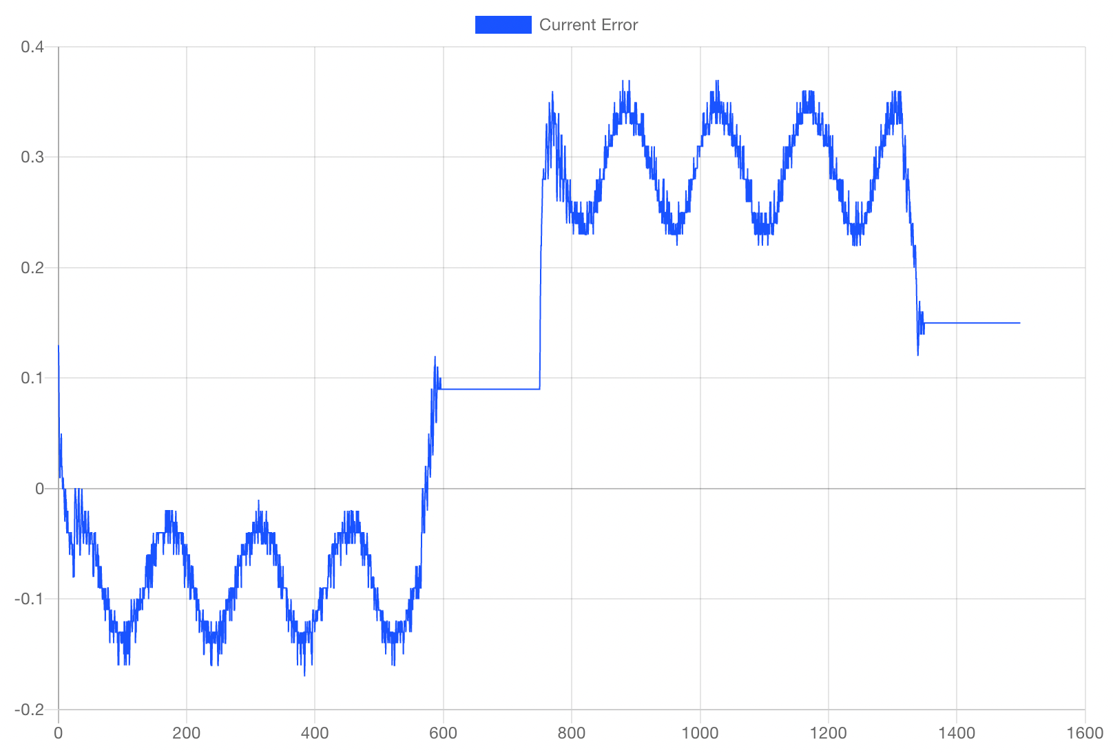
Backlash is now measured consistently closer to 0.06 steps.
It's still fascinating to me that straight, constant-speed movement is...not. If anyone has any idea why that is, I'm all ears. I'd love to understand more.
That said, I'm now making headway on closed loop tuning. As a bit more realistic test, I took the outer perimeter from layer 42 of a Benchy, sliced at 150mm/sec. With some preliminary tuning, closed loop error looks like this:
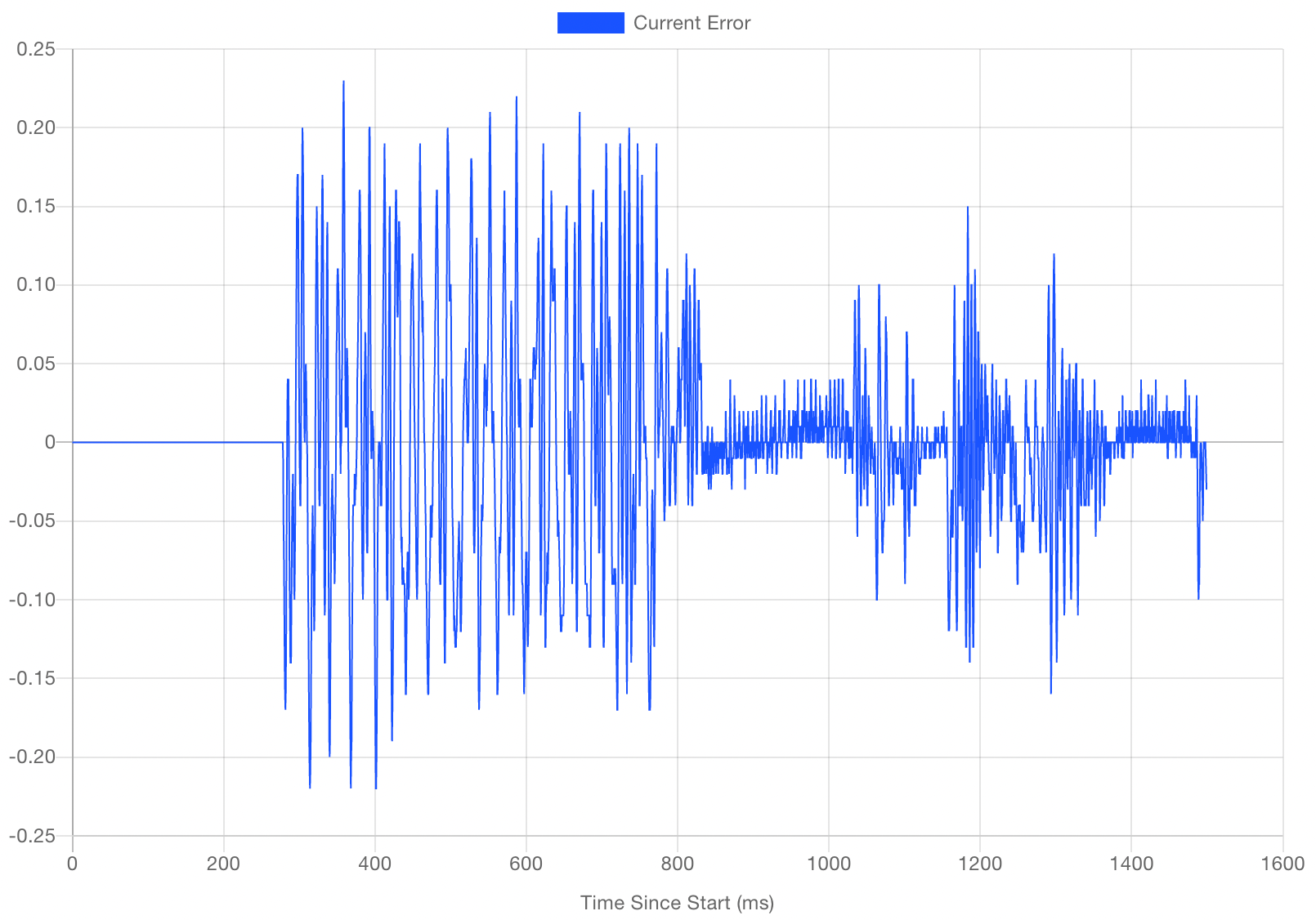
The squiggles in the first half are the rear nameplate of the Benchy where it reads "#3DBenchy," while the right half is the smoother bow.
For comparison, open loop looks like this:
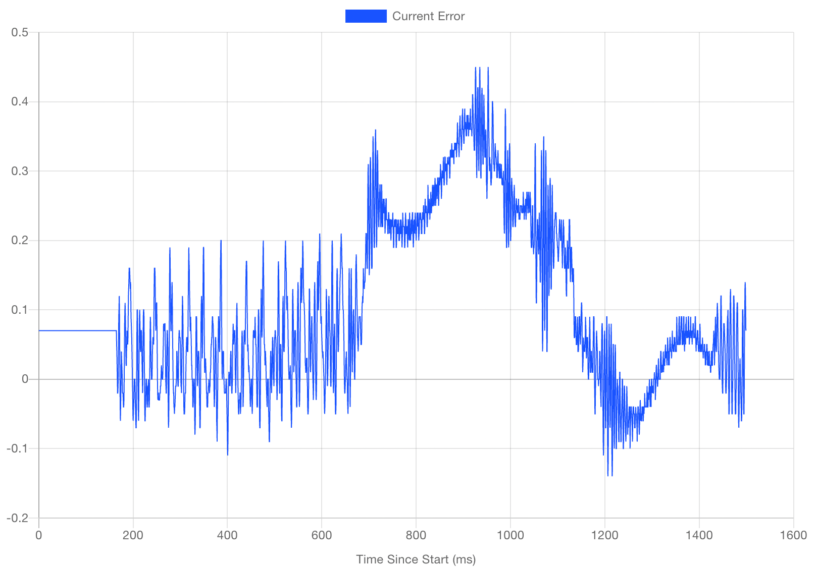
Closed loop is is staying within 0.2 steps in the worst case, with the mean error centered right at zero. Open loop strays to around 0.45 steps error, with significant offset from zero.
Pretty fascinating stuff.
-
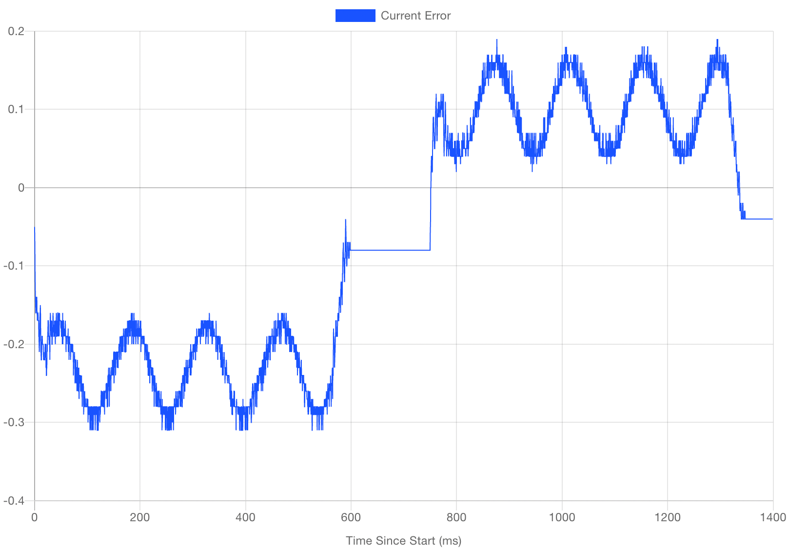
@dc42 Here is the same motion at various currents. Both steppers move the same now.
TL;DR while increasing current reduces the absolute error, it doesn't look like it makes much difference to the amplitude of the sawtooth.
I've also tried all manner of other settings on the Trinamic drivers -- TBL, TOFF, hysteresis, CoolStep, etc. Ditto for accel and jerk. No difference.
Anything else you'd like me to try?
There are all two rotations forward then back at 200mm/sec, open loop, belts removed.
1.0A
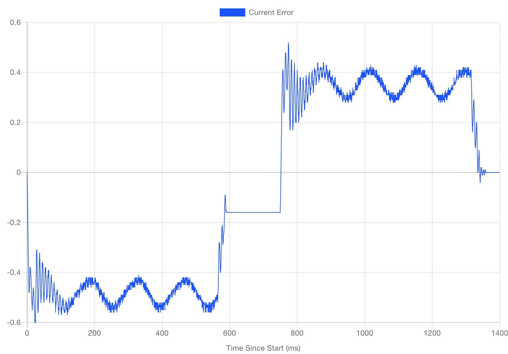
2.0A
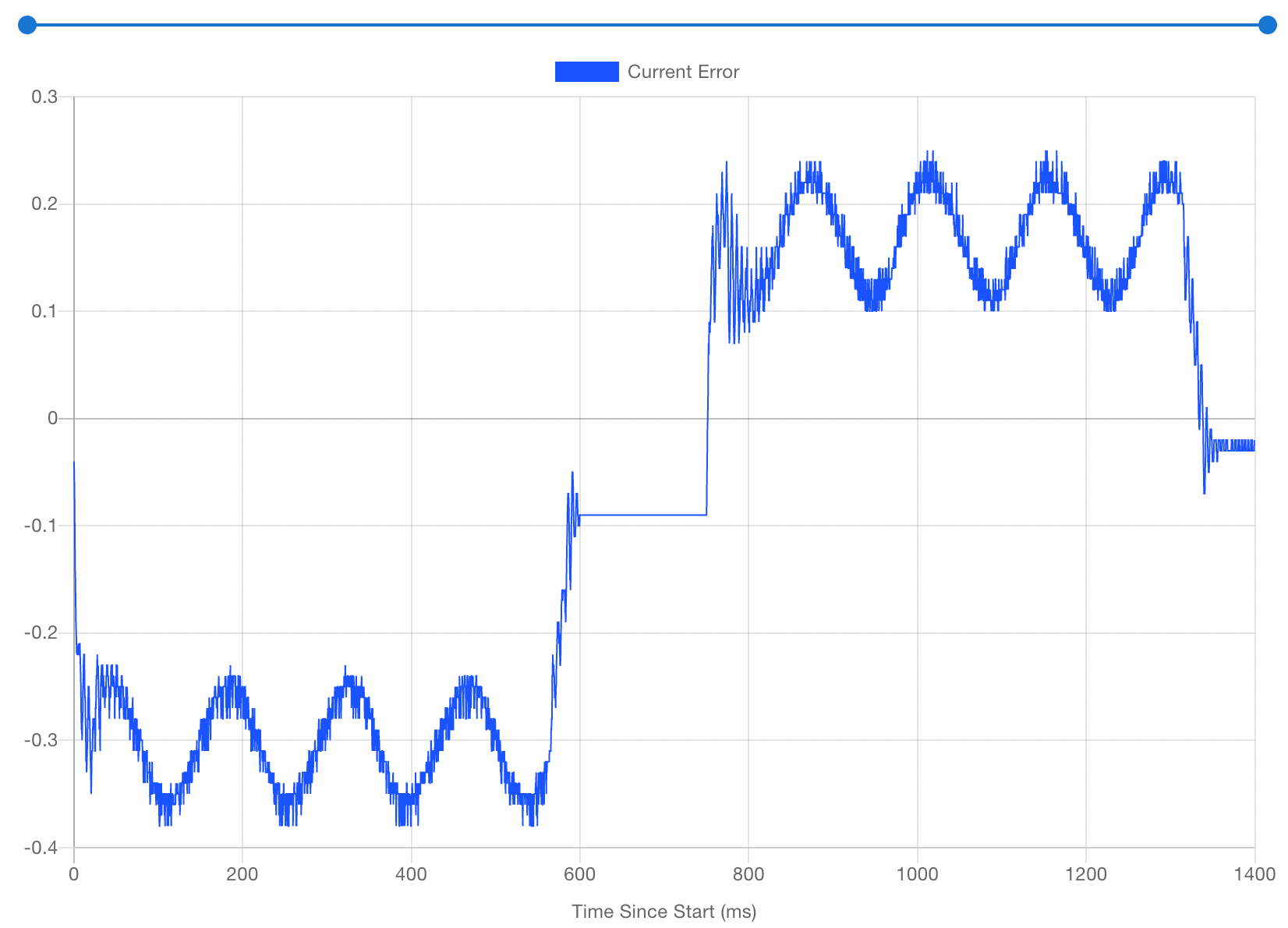
3.0A
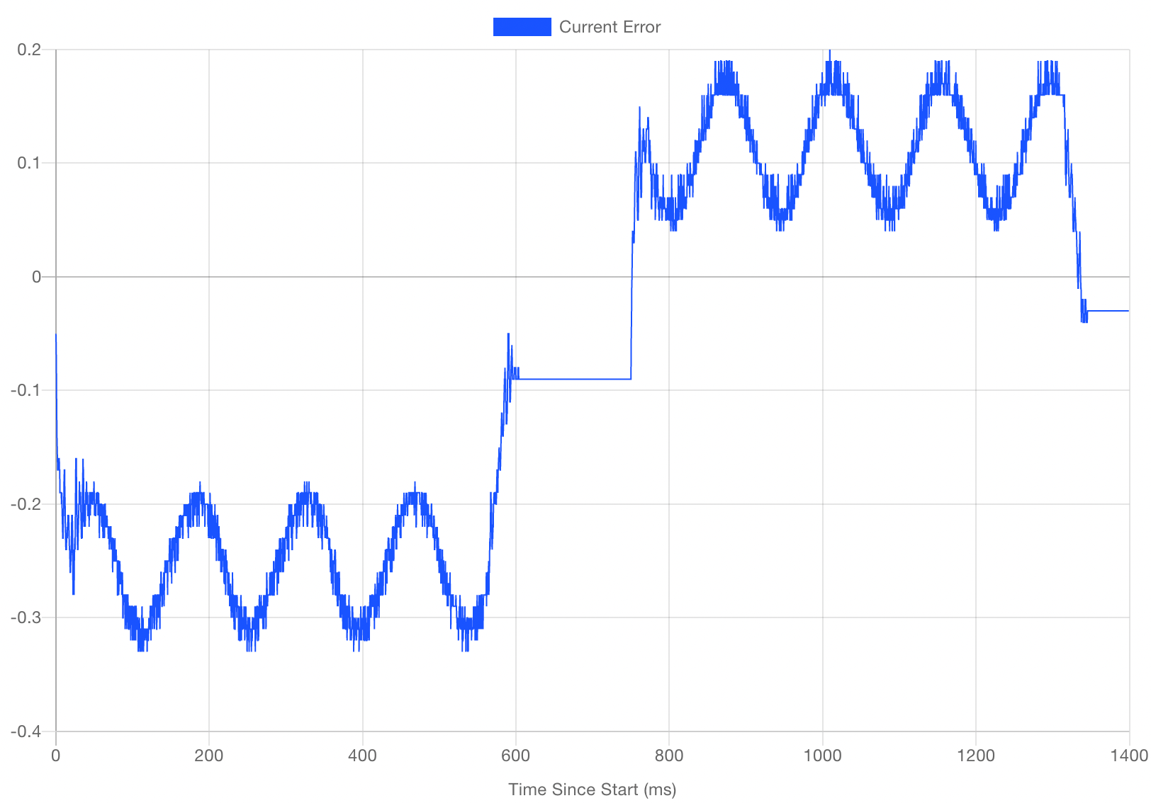
3.5A
-
@evan38109 looks like current doesn't affect the oscillation in the errors, at the currents you were using and higher.
Is the period definitely 2 cycles per revolution, not 1? If it was 1 then that could be explained by the optical disc not being exactly concentric with the shaft.
-
@dc42 Yep, the period is definitely two cycles per revolution. It's also consistent on all motors and encoders I have, including 0.9 degree steppers and CUI AMT10E2 capacitive encoders.
Here's just one revolution out and back. I marked the shaft and watched as it went. At this scale (and with the other issue resolved), it's more of a
sinecosine wave than a sawtooth pattern. Between that and the two cycles per revolution period, makes me think it has something to do with pi, but I couldn't guess what.