Problems wiring & configuring fans
-
@ce72 you'd wire it as you have your fan. The output from the PWM to analog would then go to the VSR for the speed. Then just configure it as a normal fan
-
@jay_s_uk so if I understand you correctly that would be
"out4" jumper in VFused
pin1 = GND:Ground
pin2 = VCC:DC 12V-30V
pin3 = PWM:Positive of PWM input signal
pin4 = GND:Negative of input signal"fan control board"
VSR = VOUT:Output Voltage 0-10V
GND = GND:Output Voltage Ground
PG = Not connectedIs this is for the 24v version of the Cpap?
You also mentioned earlier about the frequency on the E3d fan? how do I determine this value and could this be the reason for it not working at the moment
Thank you for all your help it is very much appreciated, As I feel like I have been banging my head against a brick wall trying to work this out

-
@ce72 "Qnn (optional) PWM frequency in Hz. Valid range: 0-65535, default: 500 for GpOut pins, 250 for fans and heaters"
-
@ce72 no, it would be provide 24v directly to the VSR from your PSU.
connect between V_OUTLC1 (+) and out4 (-) to the input of the PWM to analog converter.
the PWM to analog would then just need to connect the + and - to the VSR 0-5v input and ground. Make sure you set the PWM to analog to 5v mode rather than 10v. -
@jay_s_uk oh fair enough, thank you for pointing that out, I will check the output before fully conecting them up.
I'll post back with the outcome when the convertor arrives
thank you again
-
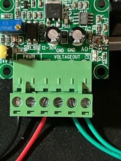
@ce72 I have received my PWM to voltage converter and I'm have troubles connecting it and getting the right output. I have checked the port on the board with a pigtail and multimeter and I'm getting the right output from there as it is the same as the other ports which are now working.
Here is how I'm trying to connect the converter
port6
V_OUTLC1 red wire to 12-30V on the converter
OUT6(-) black wire to PWM- on the converteryellow & blue going to the multimeter (leave other components out of the way)
I'm only getting 0.2v out

Please advise (I've managed to get the acceleromter working no problem, but I'm getting beaten by a fan
 )
) -
@ce72 what have you connected the PWMIN+ wire on the converter to? And the GND side of the 12-30V power input?
PS - also, which of the 2 drivers on that page linked to in the original post are you using with it: the 12V one or the 24V one?
-
@dc42 Hi, I've got the 24v variant, so I could provide power straight from the PSU.
Regarding the wiring, I tried connecting:
6HC (out5) converter
pin1 (GND) GND on the 12-30V side
pin2 (VIN) 12-30V
pin3 (out5.tach) PWM +
pin4 (out5) PWM -I had a multimeter across AO and ground on the output, (rather than connecting anything else) and had an output of 0 - 0.48V that varied with the "s" parameter.
VIN was 23.9V on the same multimeter
I hope this helps to find where I have gone wrong
-
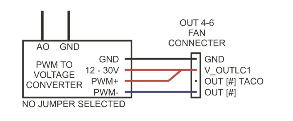
@ce72 PWM+ needs to be connected to +5V (if you have the jumper on the convertor set to 5V) or VIN (if you have the jumper on the converter removed so that it can accept 24V). Do not connect anything to the out5.tach pin unless the fan has a tacho output.
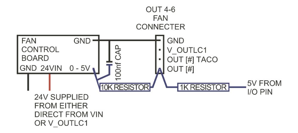
As an alternative to using the PWM-to-voltage converter, the following may work (the driver description on that site gives very limited details, so it's hard to be sure):
- Connect the fan driver power wires as now (negative to GND and positive to VIN, either directly or on the fan connector, with the fan voltage jumper set appropriately)
- Connect a 1K resistor between out5_neg and +5V (you can find +5V on the IO_ connectors)
- Connect a 10K resistor between out5_neg and fan 0-5V in
- Also connect a capacitor of 100nf (0.1uf) or greater between fan 0-5V and ground
- In the M950 command for that fan, set the frequency (Q parameter) to the maximum, which is 65535
-
@dc42 Sorry to be a pain but to clarify. and so that I fully understand, Am I right with these two options in sketch form:

OR

-
@ce72
I wired up the PWM to voltage converter as above, and found I needed the jumper to get an output. So I put the jumper in the 24v side and I was able to tune the voltage down to around 6.5v output, from this i added a "F" value on the M106 line of my config file to limit the output to the required 5v with full control.I'm pleased to say all is now working great
 I will also order the required risistors and cap to try the other way, to make a cleaner install and not need the work around in the config.