Configure multiple bed heaters
-
Hi,
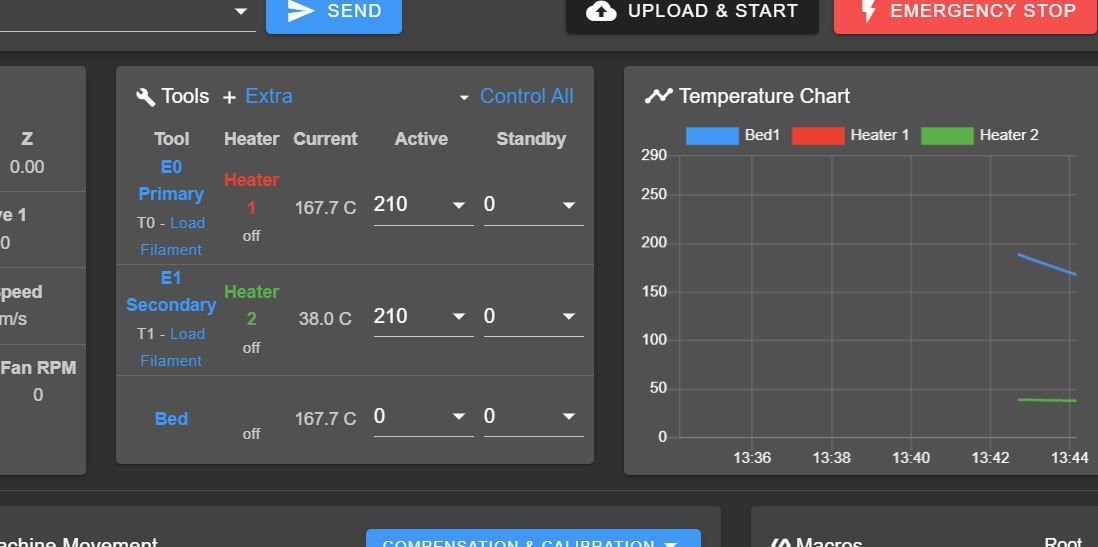
I'm trying to configure a multiple bed heaters setup, however i'm not succeeding in getting the bed heaters to show up in the DWC and Paneldue.
My specific heater config looks like :
; Heaters___________________________________________________________

; Bed1 parameters
M140 P0 H0
M305 P3 S"Bed1" X150 T"J"  ; Set thermocouple heater 0 = bed 1 thermocouple = J type
M143 H0 S125 ; Set temperature limit for heater 0 to 125C

; Bed2 parameters
M140 P3 H6
M305 P3 S"Bed2" X151 T"J"  ; Set thermocouple heater 0 = bed 1 thermocouple = J type
M307 H6 B1 S1.00
M143 H6 S125 ; Set temperature limit for heater 0 to 125C

; Bed3 parameters
M140 P4 H7
M305 P3 S"Bed3" X152 T"J"  ; Set thermocouple heater 0 = bed 1 thermocouple = J type
M307 H6 B1 S1.00
M143 H6 S125 ; Set temperature limit for heater 0 to 125C

;E0_________________________________________________________________
M305 P1 T100000 B4725 C7.060000e-8 R4700                     	    ; Set thermistor + ADC parameters for heater 1
M143 H1 S285                                                        ; Set temperature limit for heater 1 to 285C

;E1_________________________________________________________________
M305 P2 T100000 B4725 C7.060000e-8 R4700                       	    ; Set thermistor + ADC parameters for heater 2
M143 H2 S285                                                        ; Set temperature limit for heater 2 to 285C
and for completion, the complete config looks like :
; General preferences_______________________________________________
G90                                          				; Send absolute coordinates...
M83                                         				; ...but relative extruder moves
M111 S0 													; Debug off
M555 P2 													; Set output to look like Marlin
M575 P1 B57600 S1											; Set auxiliary serial port baud rate and require checksum (for PanelDu

; Network________________________________________________________ֹֹֹֹֹ___
M550 P"Big Meter - Kverneland Group"                          							; Set machine name
;M551 P"MODIX3D"               										; Set password (optional)
M552 S1                                 							; Enable network
;M552 P0.0.0.0														; Uncomment this command for using Duet Ethernet board
M586 P0 S1                                							; Enable HTTP
M586 P1 S0                               					    	; Disable FTP
M586 P2 S0                                							; Disable Telnet

; Drives
;Main board______________________________________________________________________
M569 P0 S0                                                     		; Physical drive 0 . X1
M569 P1 S1                                                       	; Physical drive 1 . X2
M569 P2 R-1                                                        	; Physical drive 2 . Canceled
M569 P3 S1                                                       	; Physical drive 3 . Main Extruder
M569 P4 S0                                                       	; Physical drive 4 . Secondery Extruder
;Duex5 board_____________________________________________________________________
M569 P5 S0                                                       	; Physical drive 5 . Y
M569 P6 S0                                                       	; Physical drive 6 . Z1 (0,1000)
M569 P7 S0                                                       	; Physical drive 7 . Z2 (0,0)
M569 P8 S0                                                       	; Physical drive 8 . Z3 (1000,0)
M569 P9 S0                                                       	; Physical drive 9 . Z4 (1000,1000)
;___________________________________________________________________
M584 X0:1 Y5 Z6:7:8:9 U1 E3:4 P3									; Driver mapping
M671 X-181:-181:1049:1049 Y1066:-58:-58:1066 S10    			  	; Anticlockwise
;___________________________________________________________________
M350 X16 Y16 Z16 E16:16 U16 I1                                		; Configure microstepping with interpolation
M92 X100.00 Y100.00 Z2000.00 E440.530:418.500 U100.00      			; Set steps per mm
M566 X240 Y360 Z30.00 E120.00:120.00 U240 P1                    	; Set maximum instantaneous speed changes (mm/min)
M203 X9000.00 Y9000.00 Z200.00 E1200.00:1200.00 U9000.00    		; Set maximum speeds (mm/min)
M201 X1000 Y1000 Z120.00 E250.00:250.00 U1000             			; Set accelerations (mm/s^2)
M204 P500                                      						; Set print and travel accelerations  (mm/s^2)
M906 X1800 Y1800.00 E1000.00:1000.00 U1800 I40 						; Set motor currents (mA) and motor idle factor in per cent
M906 Z1800.00 I50 													; Set motor currents (mA) and motor idle factor in per cent
M84 S60 X Y U E0 E1                                                 ; Set idle timeout - one minute

; Axis Limits_______________________________________________________
M208 X0:1000 Y0:1000 Z0:1000 U0:1000		                        ; Set axis minima and maxima

; Endstops__________________________________________________________
M574 X1 Y2 U1 S1                                            		; Set active low and disabled endstops

; Z-Probe___________________________________________________________
M574 Z2 S2                                                     		; Set endstops controlled by probe
M307 H7 A-1 C-1 D-1                                     			; Disable heater on PWM channel for BLTouch
M558 P9 H5 F120 T9000 A1 R0.7            			       			; Set Z probe type to bltouch and the dive height + speeds
G31 P500 X-14 Y21 Z1.284  	                    		     		; Set Z probe trigger value, offset and trigger height(Z-Offset)
M557 X-14:974 Y21:1009 S52 		                        			; Define mesh grid. 400 Points
M376 H30			                    							; Height (mm) over which to taper off the bed compensation

; Heaters___________________________________________________________
;M140 H-1                                                            ; Disable heated bed
;M307 H0 A-1 C-1 D-1												 ; Disable heater on PWM channel

; Bed1 parameters
M140 P0 H0
M305 P3 S"Bed1" X150 T"J"  ; Set thermocouple heater 0 = bed 1 thermocouple = J type
M143 H0 S125 ; Set temperature limit for heater 0 to 125C

; Bed2 parameters
M140 P3 H6
M305 P3 S"Bed2" X151 T"J"  ; Set thermocouple heater 0 = bed 1 thermocouple = J type
M307 H6 B1 S1.00
M143 H6 S125 ; Set temperature limit for heater 0 to 125C

; Bed3 parameters
M140 P4 H7
M305 P4 S"Bed3" X152 T"J"  ; Set thermocouple heater 0 = bed 1 thermocouple = J type
M307 H6 B1 S1.00
M143 H6 S125 ; Set temperature limit for heater 0 to 125C

;E0_________________________________________________________________
M305 P1 T100000 B4725 C7.060000e-8 R4700                     	    ; Set thermistor + ADC parameters for heater 1
M143 H1 S285                                                        ; Set temperature limit for heater 1 to 285C
;M307 H1 A# C# D# V# S1.0 B0                            			; PID calibration
;E1_________________________________________________________________
M305 P2 T100000 B4725 C7.060000e-8 R4700                       	    ; Set thermistor + ADC parameters for heater 2
M143 H2 S285                                                        ; Set temperature limit for heater 2 to 285C
;M307 H2 A# C# D# V# S1.0 B0                             	   		; PID calibration


; Fans______________________________________________________________
M106 P0 S0 I0 F500 H-1 C"E0 BlowerFan"                       	    ; Set fan 0 value, PWM signal inversion and frequency. Thermostatic control is turned off
M106 P1 S0 I0 F500 H-1 C"E1 BlowerFan"                              ; Set fan 1 value, PWM signal inversion and frequency. Thermostatic control is turned off
M106 P5 T46 H1 							    						; Set fan 5. Thermostatic control is turned on
M106 P6 T46 H2 							   							; Set fan 6. Thermostatic control is turned on
M106 P2 I-1                                                         ; LED (optional)
M106 P3 I-1                                                         ; LED (optional)
M106 P4 I-1                                                         ; LED (optional)
M106 P7 I-1                                                         ; Main LED
M106 P8 I-1                                                         ; LED (optional)

; Tools
;T0_________________________________________________________________
M563 P0 S"E0 Primary" D0 H1 F0                      				; Define tool 0
G10 P0 X0 Y0 Z0                                   					; Set tool 0 axis offsets
G10 P0 R0 S210                                		  				; Set initial tool 0 active and standby temperatures to 0C
;T1_________________________________________________________________
M563 P1 S"E1 Secondary" D1 H2 F1                     			    ; Define tool 1
G10 P1 X0 Y49 Z0                             			    		 ; Set tool 1 axis offsets
G10 P1 R0 S210                               		     	 		; Set initial tool 1 active and standby temperatures to 0C

; Automatic power saving____________________________________________
M911 S22.5 R29.0 P"M913 X0 Y0 G91 M83 G1 Z3 E-5 F1000"              ; Set voltage thresholds and actions to run on power loss. Power Failure Pause

; Custom settings___________________________________________________
M591 D0:1 P1 C4 S1		   			       	    					; Regular filament sensor for E0 and E1
;M564 H0 S0                                                	    	; Negative movements are allowed
Bed heater 2 and 3 don't appear in the DWC and Paneldue( bed heater H0 does ).
Looking at the diagnostics ( M122 ), the heaters seem to be correctly defined
=== Bed heaters = 0 -1 6 7
What am i doing wrong? Why are they not displayed? Giving them a name ( as noted in the docs M305 S parameter ) does not seem to help unfortunately.
-
What firmware version on the duet, paneldue? What DWC version?
Can you send M122 and M98 P"config.g" and post the results here?
-
This post is deleted! -
@phaedrux Thanks for your response
As requested :
Duet firmware version : 2.05
DWC version : 2.07M122 output :
( had to do it like this, otherwise it's marked as spam? )M98 P"config.g" output :
M98 P"config.g" HTTP is enabled on port 80 FTP is disabled TELNET is disabled Warning: Heater 6 appears to be over-powered. If left on at full power, its temperature is predicted to reach 365C. Error: M106: Fan 2 is disabled Error: M106: Fan 3 is disabled Error: M106: Fan 4 is disabled Error: M106: Fan 7 is disabled Error: M106: Fan 8 is disabled -
I think to have the additional bed heaters show up correctly you'd need to upgrade your firmware to RRF3, including the PanelDue.
-
Unfortunately we are unable to upgrade to RRF3 yet.
But I think it must be possible to configure RRF2 using multiple bed heaters to show up in the DWC and Paneldue?
According to this post, is must be possible : https://forum.duet3d.com/topic/3516/using-multiple-bed-heaters/21 -
@bart1992 you should be able to configure them in RRF 2.05 and you may get them to show up in DWC, but they certainly won't show up in PanelDueFirmware 1.x.
-
@bart1992 whats stopping you upgrading to RRF3?
-
Thank you for responding.
Can you explain how I should let them show up in the DWC?
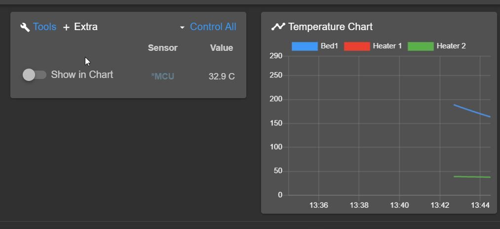
Currently only bed1 is shown ( see attachment )!

-
@bart1992 I guess DWC 2.0.7 doesn't support multiple bed heaters. Probably that's because the status report that DWC 2 and earlier use doesn't have multiple values for bed heaters. DWC 3 uses the RRF3 object mode instead and does support multiple bed heaters.