Which frame design can scale best?
-
@kuon ballscrews are a lot more expensive than belts, and unless you have really long axis' you are not going to see the benefits (they are mostly good for really high loads, far greater than an FDM printer). So long as you increase the belt width, they work well to quite long runs. Screw-drive works well if you really need that extra stiffness.
The crossed gantry doesn't scale well (it's not a commonly used design). H-bot and the MarkForged style gantry give you better weight savings. CoreXY will save a little more weight and space at the expense of a very complex belt system.For a 600x3 machine I'd do either H-bot or MarkForged gantry. Maybe servo's, but going to big NEMA-23's with big pulleys will get you plenty of speed without a noticable drop in resolution.
-
@kuon
 for ballscrews
If you're afraid of belt stretch, check out the Shapeoko CNC machines. They have the shortest belts of all designs I've seen.
You'd have moving steppers, but the mass of the extruder is much higher. You shouldn't copy their V-wheel motion system. It'll work with linear rails, too.
Since you're planning to use water cooling, you can also cool the steppers which run inside the enclosure. -
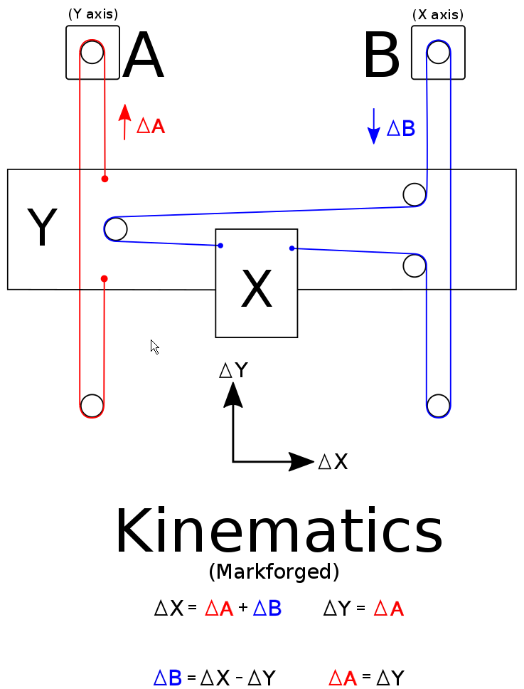
@theruttmeister The MarkForged gantry style is like the craftbot? The X steppers are moving along the Y axis? That was my first design.
For the ball screw I thought it would be bring good stability for a large heavy extruder head, and I found this "workhorse" printer which uses screw, so I thought screws were cool. (even if I planned ballscrew and not leadscrew).
For belts, GT2 is usually used, but GT3 is available in larger size, do you think there would be precision drawback with GT3? I could also double the GT2 if needed.
-
@kuon said in Which frame design can scale best?:
The MarkForged gantry style is like the craftbot? The X steppers are moving along the Y axis? That was my first design.
Here is the MarkForged layout. I built one but added a second Y stepper (which would be to the right of the X stepper in this diagram) so both ends of the gantry were driven by a stepper. I did this because I was concerned about racking.
The printer works well.
Frederick
-
@fcwilt Thank you, I didn't know this kinematic.
-
@kuon I used a ball screw and 23 size stepper motor to drive the Y axis in a bed flinger printer a few years ago. It had a horrible resonance problem that I could not cure. Though it could easily drive the mechanism at 150 mm/sec, I had to limit print speed to 40 mm/sec to avoid the resonance that occurred at 50 mm/sec. I know ball screws are used in industrial mechanisms all the time, so surely I was doing something wrong, but I never figured it out what it was and converted the machine back to belt drive.
Have you considered a belt lifted Z axis? Belts can cheaply scale to any size you want (as long as you're willing to pay for the guide rails) in all axes, and don't require lubrication. Belt stretch is small enough that it isn't really an issue in the Z axis, and at 600x600 mm, probably not in X and Y either. The "tricky" part is preventing the bed or gantry from dropping when power is cut, and that's easily/cheaply solved with a worm gear drive reducer.
@fcwilt I know it's just a sketch, but I hope your mechanism isn't built exactly like the drawing - the X axis belt should be parallel to the X axis guide rail(s)...
-
@mrehorstdmd Ok, I guess belts makes sense. I am looking at misumi belt lines and they have tons of different profiles. Do you know if any other that GT2 is appropriate? As I need high temperature, it would help if other profiles works too.
As for the Z axis, I thought of using belts if I go belts, and depending on what motor I use, I will put brakes/worm gear. -
@kuon Check out Gates 2GT belts. If you are worried about stretching, step up to 9mm wide - that's what we use for our printers (which are scalable) for all axes. Our largest (so far) is 400mm x 400mm x 600mm.
You mention high temp. How high do you need? Our printers are rated to 80c, so we went with the standard belts which are also rated for 80c, but Gates also makes an EPDM line which are rated to 135c.
Modest plug - we will be opening our online parts store in Jan 2022 and will carry both 6mm and 9mm Gates belts, pulleys, and smooth / toothed idlers. We also will offer the class H (high temp - rated for 180c) LDO steppers used in our printers, which includes our custom high torque z-steppers with integrated brake.

-
@mrehorstdmd said in Which frame design can scale best?:
@fcwilt I know it's just a sketch, but I hope your mechanism isn't built exactly like the drawing - the X axis belt should be parallel to the X axis guide rail(s)...
Just an image found using a Google search. It didn't occur to me that @kuon might take it literally - I should have pointed out what you mentioned.
Thanks.
Frederick
-
@kuon said in Which frame design can scale best?:
As for the Z axis, I thought of using belts if I go belts, and depending on what motor I use, I will put brakes/worm gear.
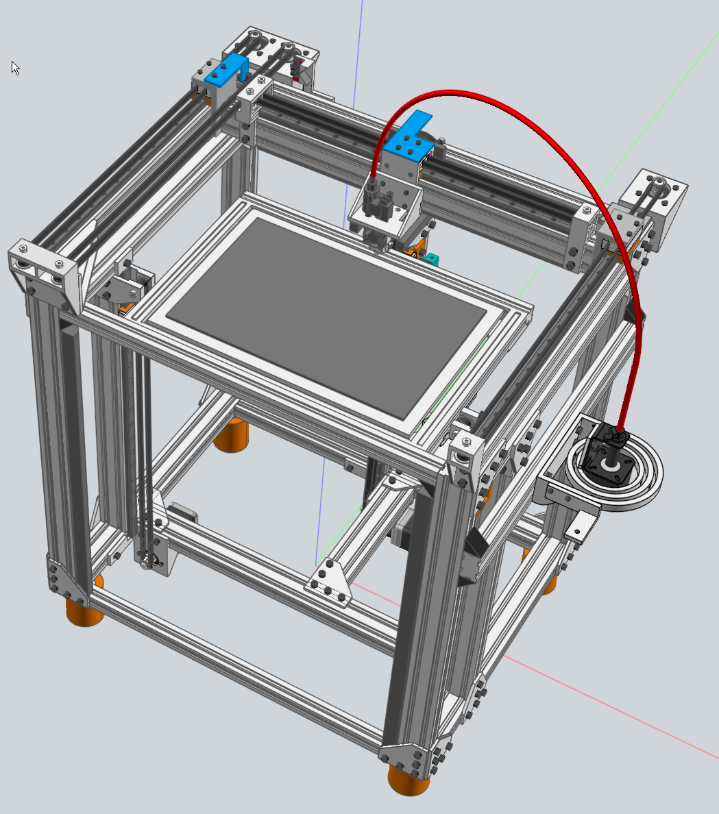
Here is a quick-and-dirty video of my implementation of a Mark Forged type of printer. The video was made to demonstrate the bed leveling ability of multiple Z steppers.
It was also a test bed for belt drive for the Z axis. Since the Z axis usually doesn't need to be fast but you don't want the bed to fall when power is removed I used steppers with integrated 5 to 1 planetary gearboxes.
I'm so pleased with the result of using belt drive I will likely use it on any new printer I build.
Here is a overview of the printer which better shows the Mark Forged kinimatics:
-
@kuon I used one of these in my printer's belt lifted Z axis and it works very nicley: https://www.ebay.com/itm/191714031261?epid=711126295&hash=item2ca30bf69d:g:A7UAAOSwPhdVB2f0
The gears are about as good as you can get, don't create any print artifacts, and the 30:1 ratio prevents bed drop when power is cut. With the pulleys I used it provides a nice, round, 20 um/full step.
The problem with planetary gear reductions is they usually (always?) have very odd gear ratios that make it impossible to print layers in full step multiples (in case that matters to you). Here's a classic example:
https://www.ebay.com/itm/231616316474?epid=1540009596&hash=item35ed68843a:g:B9wAAOSw9N1VmkMZ
As Tom Waits says, "The large print giveth, and the small print taketh away". The big print says it's a 5:1 gear box, but if you look at the specs, it's actually 5+2/11:1. There is no "neat" full-step-multiple layer thickness available with that. I would be wary of any planetary geared motor that provides only the big print number without seeing a detailed spec sheet that shows the actual ratio.OTOH, maybe it isn't really necessary to print layers in full-step multiples.
Someone at the makerspace built a corexy printer with a belt lifted Z axis using this type of motor/gearbox and it produces beautiful prints: https://www.aliexpress.com/item/1005001763231566.html?spm=a2g0o.productlist.0.0.1b0c182eqynHM6&algo_pvid=29493bf2-624e-4829-882a-4d4b452de7ce&algo_exp_id=29493bf2-624e-4829-882a-4d4b452de7ce-41&pdp_ext_f={"sku_id"%3A"12000017469607760"}
-
@mrehorstdmd said in Which frame design can scale best?:
The problem with planetary gear reductions is they usually (always?) have very odd gear ratios that make it impossible to print layers in full step multiples (in case that matters to you).
You are correct in that they often have odd gear ratios but you can find them in ratios that may be preferred. The cheaper ones I tried at first just as proof of concept had a ratio like you mentioned. But once I was satisfied that the concept was sound I researched more expensive units and found true 5 to 1.
Frederick
-
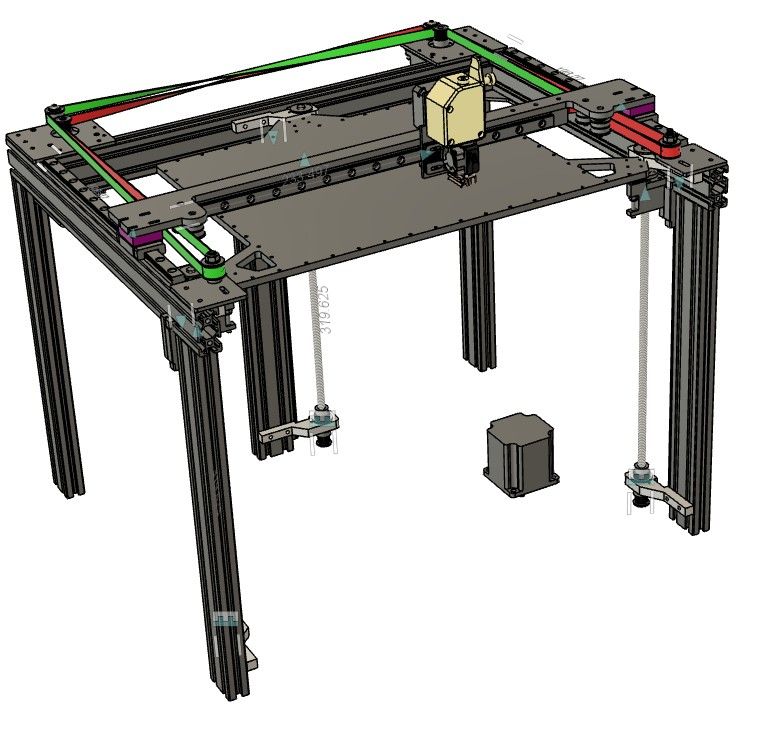
Very interesting discussion topic. I'm working on a printer design myself, and although it's not the large scale you are thinking about I've designed it without any restrictions on X Y or Z. At present its capacity is 250 x 300 x250 tall), Its a coreXY with a "twisted belt" design. I've worked hard to minimize belt offsets form rail axes for both the X and Y rails. My belief is that minimum offsets lead to minimum moment arms and therefore minimal torques during acceleration and deceleration. I've also designed to not require machined parts (so far, so good) but rely heavily on metal plates that can be laser cut (there are lots of laser job shops, my favorite is sendcutsend.com in the us - no affiliation, just a satisfied customer). It's still a work in progress, as you can see. I've built a proto top frame I'm happy with and I'm working on the Z axes now. However, the Mark Forged kinematics are vert intriguing. I might have to build one of those too...
-
-
@mikeabuilder I would love to be able to source steel easily, but here in switzerland I couldn't find a reasonably priced service that does precision steel cutting.
-
@fcwilt If I do not use the "crossed gantry" (ala ultimaker), I could also use an IDEX arrangement instead of one large head, but this would mean 2 moving steppers along Y. I need dual head, but not necessarily dual carriage.
I am still "tinkering around" but I thought of maybe using a small stepper with a rack gear to be able to lift either extruder. The following picture is just the placement, rack gear or mini belt is not present yet. Basically for probing both extruders would be in the middle position, and for printing either one would be down.
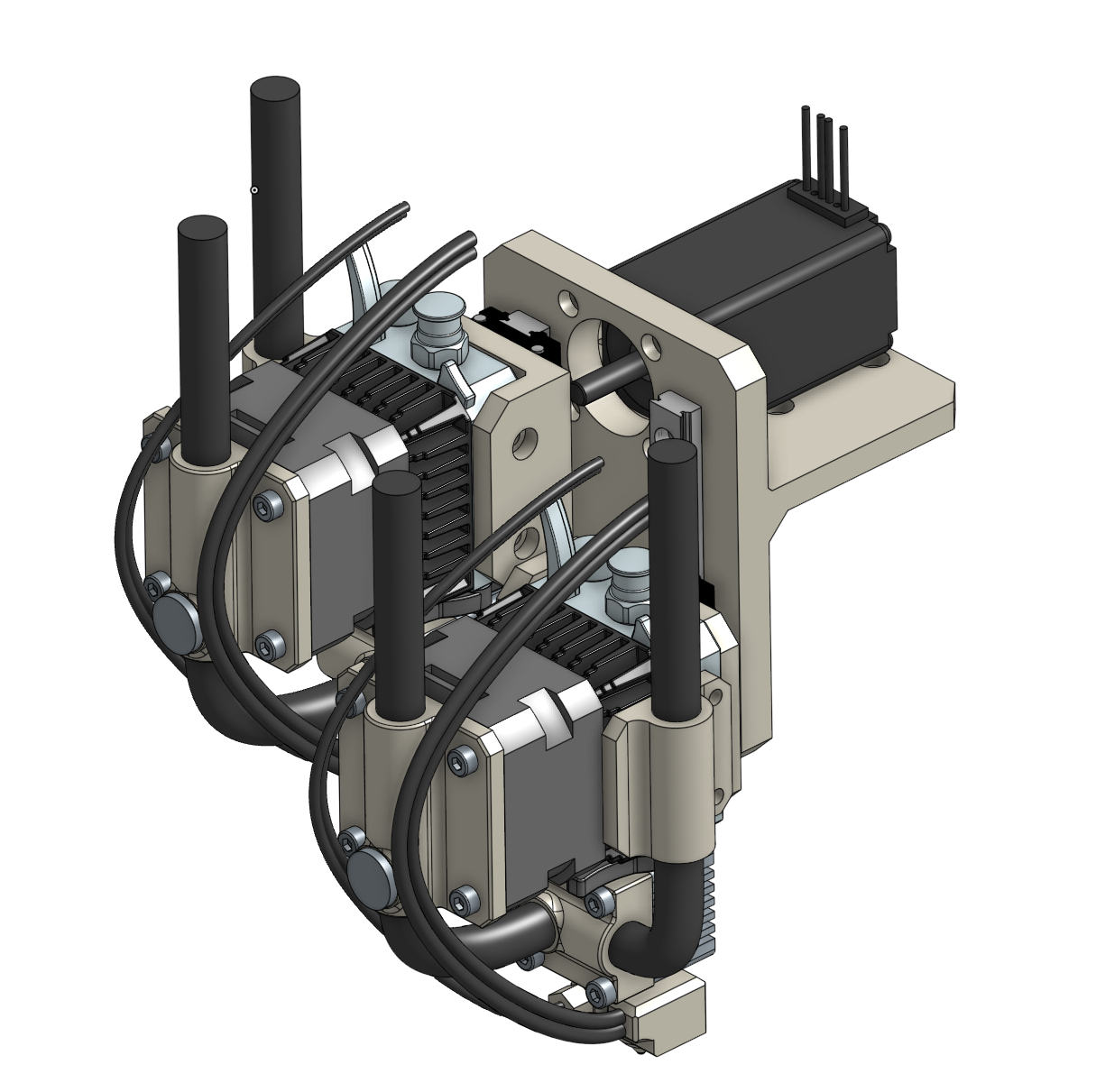
The advantage of moving one large head is that I could mount anything (pellet...) and for a large printer, it is a plus.
I love the mark forged kinematic idea, but it makes one belt very long, that's not an issue for a large printer?
-
@kuon said in Which frame design can scale best?:
I love the mark forged kinematic idea, but it makes one belt very long, that's not an issue for a large printer?
You mean the X belt?
At the time I was deciding between a CoreXY and the Mark Forged. Everyone seemed to be doing a CoreXY so I decided to be difficult - I mean different.
I never considered the X belt to be that long. I did opt for 9mm belts instead of 6.
Frederick
-
@kuon said in Which frame design can scale best?:
I am still "tinkering around" but I thought of maybe using a small stepper with a rack gear to be able to lift either extruder. The following picture is just the placement, rack gear or mini belt is not present yet. Basically for probing both extruders would be in the middle position, and for printing either one would be down.

What are those largish black rods for?
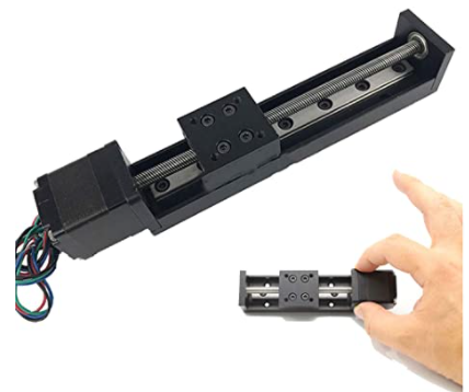
I used one these in 50mm for a recent project:
-
@fcwilt Yeah, for my frame size it is nearly a 6 meter belt. That's why I am considering a regular cartesian printer (like the craftbot flow serie), and thus maybe IDEA. At first I thought the ultimaker crossed gantry would be cool, as it allows for short belt (I would have used 4 steppers, 2 per axles).
-
@fcwilt Black rods are water cooling pipes for "illustration".