DWC Tool #s not lining up with Temp Chart
-
Board: Duet 2 Maestro (2Maestro)
Firmware: RepRapFirmware for Duet 2 Maestro 3.3 (2021-06-15)
Duet Web Control 3.4.0-b6config.g:
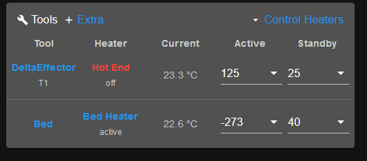
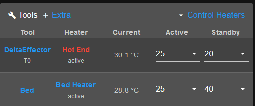
If there's anything here that looks out of the ordinary, let me know. I'm slowly adjusting to RRF3's way of doing things.; General preferences M575 P1 S1 B57600 ; enable support for PanelDue G90 ; send absolute coordinates... M83 ; ...but relative extruder moves M550 P"Griffin Delta" ; set printer name M665 R130 L288.87 B130 H229.4 ; Set delta radius, diagonal rod length, printable radius and homed height M666 X0 Y0 Z0 ; endstop adjustments here, or let auto calibration find them ; Network M552 S1 ; enable network M586 P0 S1 C"*" ; enable HTTP M586 P1 S1 ; enable FTP M586 P2 S1 ; enable Telnet ; Drives M569 P0 S0 ; physical drive 0 goes backwards M569 P1 S0 ; physical drive 1 goes backwards M569 P2 S0 ; physical drive 2 goes backwards M569 P3 S1 ; physical drive 3 goes forwards M584 X0 Y1 Z2 E3 ; set drive mapping M350 X16 Y16 Z16 E16 I1 ; configure microstepping with interpolation M92 X80.00 Y80.00 Z80.00 E506.92 ; set steps per mm M566 X12000.00 Y12000.00 Z12000.00 E1200.00 ; set maximum instantaneous speed changes (mm/min) ---was 1200 M203 X18000.00 Y18000.00 Z18000.00 E2400.00 ; set maximum speeds (mm/min) M201 X5000.00 Y5000.00 Z5000.00 E1000.00 ; set accelerations (mm/s^2) -- was 1000 M906 X1000 Y1000 Z1000 E1100 I30 ; set motor currents (mA) and motor idle factor in per cent M84 S30 ; Set idle timeout ; Axis Limits M208 Z0 S1 ; set minimum Z ; Endstops M574 X2 S1 P"xstop" ; configure switch-type (e.g. microswitch) endstop for high end on X via pin xstop M574 Y2 S1 P"ystop" ; configure switch-type (e.g. microswitch) endstop for high end on Y via pin ystop M574 Z2 S1 P"zstop" ; configure switch-type (e.g. microswitch) endstop for high end on Z via pin zstop ; Z-Probe M558 P1 X0 Z0 H5 F120 T5000 C"zprobe.in+zprobe.mod" ; Set Z probe type to dc42 IR_PROBE G31 P450 X18 Y18 Z0.934 ; set Z probe trigger value, offset and trigger height M557 R75 S20 ; define mesh grid ; Bed Heater M308 S0 P"bedtemp" Y"thermistor" T100000 B4138 A"Bed Heater" ; configure sensor 0 as thermistor on pin bedtemp M950 H0 C"bedheat" T0 ; create bed heater output on bedheat and map it to sensor 0 M307 H0 B0 S0.90 ; use PID tuning for the bed heater and set PWM limit M140 H0 ; map bed to heater 0 M140 S-273 R40 ; turn off bed heater (set to abs zero) but set standby temp to 40 M143 H0 S120 ; set temperature limit for heater 0 to 120C ; Hot End Heater M308 S1 P"e0temp" Y"thermistor" T100000 B4138 A"Hot End" ; configure sensor 1 as thermistor on pin e0temp M950 H1 C"e0heat" T1 ; create nozzle heater output on e0heat and map it to sensor 1 M307 H1 B0 S0.90 ; use PID tuning for the heater and set PWM limit M143 H1 S280 ; set temperature limit for heater 1 to 280C ; Fans Q30000 Q1000 M950 F0 C"fan0" ; Layer fan on pin fan0 and set its frequency M106 P0 S0 H-1 C"Print Layer Fan" ; set fan 0 starting speed. Thermostatic control is disabled M950 F1 C"fan1" ; Heat sink fan on pin fan1 and set its frequency M106 P1 S1 H1 T45 C"HotEndFan" ; set fan 1 value. Thermostatic control is turned on ; Tools M563 P1 S"DeltaEffector" H1 F0:1 ; define tool 1 with heater 1 and Fans 0&1 G10 P1 R25 S125 ; Active 125 Standby 25 ;M568 P0 R20 S25 A0 ; replaces g10; Set tool 0 Active/Standby=150C/25C and Current State = Off R25 S150 A0 G10 P1 X0 Y0 Z0 ; set tool 0 axis offsets ; Miscellaneous M501 ; load saved parameters from non-volatile memory M911 S10 R11 P"M913 X0 Y0 G91 M83 G1 Z3 E-5 F1000" ; set voltage thresholds and actions to run on power loss T0 ; select first toolHeater 1 active temp doesn't change DeltaEffector's temp, But Heater 0's active temp will change the bed heater. None of the links in this window work and neither temperature updates.

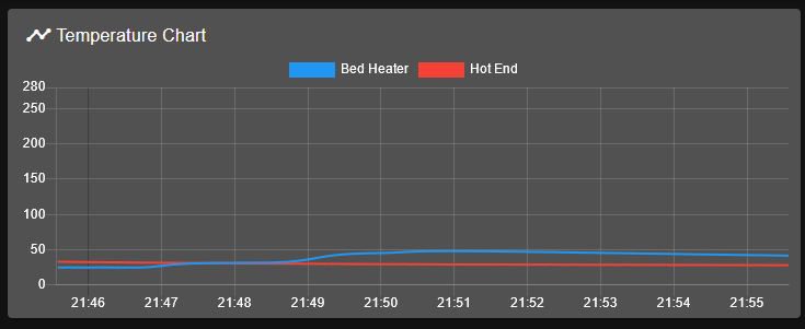
The Temperature chart graphs the correct temperatures (and names) accurately.

I don't know how to change the Tools window to show the right items. I thought it might have been a g10 vs m568 problem, but reverting to g10 didn't change anything.
This printer has been sitting idle for a couple years. Just got it out again and accidentally damaged the sd card. Updated the firmware and DWC a few times. Got most of it working as before, but now it's just fine tuning. Before being shelved, it was printing just fine.
-
@oracledude the issue is that you have tool 0 selected, but the Delta effector is set as tool 1 in the config:
@oracledude said in DWC Tool #s not lining up with Temp Chart:
M563 P1 S"DeltaEffector" H1 F0:1 ; define tool 1 with heater 1 and Fans 0&1change that to
M563 P0 S"DeltaEffector" H1 F0:1 ; define tool 0 with heater 1 and Fans 0&1and it should work as expected
-
Made the change as suggested, but the DWC didn't update. Hot End link doesn't work and both current temperatures are incorrect. Bed Heater link does work though.

; Tools
M563 P0 S"DeltaEffector" H1 F0:1 	           ; define tool 0 with heater 1 and Fans 0&1
G10 P0 R25 S125                                    ; Active 125 Standby 25
G10 P0 X0 Y0 Z0                                    ; set tool 0 axis offsets
T0                                                 ; select first tool
Interesting enough, after I made that update, the hotend now turns on at system startup. By the time the PanelDue and DWC are reconnected, the temp is already up near 70, causing a fault.
Error: Heater 1 fault: temperature excursion exceeded 15.0°C (target 125.0°C, actual 67.0°C) -
I wonder if it's because you're using firmware 3.3 and DWC 3.4beta6.
I can't see why it would show T1 on DWC for deltaeffector when it's setup as tool0 in the config. Unless that photo is from before changing the config.g?
Can you share the results of M122 and M98 P"config.g"?
-
There is no extruder defined in the tool, and two fans; is that confusing things?
Try this?
; Tools
M563 P0 S"DeltaEffector" D0 H1 F0                  ; define tool 1 with heater 0 and Fan 0
G10 P0 X0 Y0 Z0                                    ; set tool 0 axis offsets
G10 P0 R25 S125                                    ; Active 125 Standby 25
That sequence sets up tool 0 OK on my multi-tool machine.
-
m122
=== Diagnostics ===
RepRapFirmware for Duet 2 Maestro version 3.3 (2021-06-15 21:47:01) running on Duet Maestro 1.0
Board ID: 08DAM-9F9GA-J24TD-6JKD0-3S86R-KP3UT
Used output buffers: 8 of 24 (16 max)
=== RTOS ===
Static ram: 23556
Dynamic ram: 66924 of which 0 recycled
Never used RAM 25016, free system stack 164 words
Tasks: NETWORK(ready,18.1%,270) HEAT(delaying,0.1%,227) Move(notifyWait,0.1%,343) TMC(notifyWait,1.3%,117) MAIN(running,80.1%,513) IDLE(ready,0.3%,30), total 100.0%
Owned mutexes:
=== Platform ===
Last reset 00:00:57 ago, cause: power up
Last software reset at 2021-12-03 17:30, reason: User, GCodes spinning, available RAM 25016, slot 0
Software reset code 0x0003 HFSR 0x00000000 CFSR 0x00000000 ICSR 0x00000000 BFAR 0xe000ed38 SP 0x00000000 Task MAIN Freestk 0 n/a
Error status: 0x00
Aux0 errors 0,0,0
Step timer max interval 938
MCU temperature: min 16.0, current 21.1, max 21.3
Supply voltage: min 13.9, current 14.1, max 14.2, under voltage events: 0, over voltage events: 0, power good: yes
Heap OK, handles allocated/used 0/0, heap memory allocated/used/recyclable 0/0/0, gc cycles 0
Driver 0: position 38266, standstill, read errors 0, write errors 0, ifcnt 8, reads 9457, writes 8, timeouts 0, DMA errors 0
Driver 1: position 38266, standstill, read errors 0, write errors 0, ifcnt 8, reads 9457, writes 8, timeouts 0, DMA errors 0
Driver 2: position 38266, standstill, read errors 0, write errors 0, ifcnt 8, reads 9457, writes 8, timeouts 0, DMA errors 0
Driver 3: position 0, standstill, read errors 0, write errors 0, ifcnt 6, reads 9458, writes 6, timeouts 0, DMA errors 0
Driver 4: position 0, standstill, read errors 0, write errors 0, ifcnt 6, reads 9458, writes 6, timeouts 0, DMA errors 0
Driver 5: position 0, assumed not present
Driver 6: position 0, assumed not present
Date/time: 2021-12-04 13:00:16
Slowest loop: 5.74ms; fastest: 0.14ms
I2C nak errors 0, send timeouts 0, receive timeouts 0, finishTimeouts 0, resets 0
=== Storage ===
Free file entries: 10
SD card 0 detected, interface speed: 15.0MBytes/sec
SD card longest read time 2.6ms, write time 0.0ms, max retries 0
=== Move ===
DMs created 83, maxWait 45759ms, bed compensation in use: none, comp offset 0.000
=== MainDDARing ===
Scheduled moves 5, completed moves 5, hiccups 0, stepErrors 0, LaErrors 0, Underruns [0, 0, 0], CDDA state -1
=== AuxDDARing ===
Scheduled moves 0, completed moves 0, hiccups 0, stepErrors 0, LaErrors 0, Underruns [0, 0, 0], CDDA state -1
=== Heat ===
Bed heaters = 0 -1, chamberHeaters = -1 -1
Heater 0 is on, I-accum = 0.0
=== GCodes ===
Segments left: 0
Movement lock held by null
HTTP is idle in state(s) 0
Telnet is idle in state(s) 0
File is idle in state(s) 0
USB is idle in state(s) 0
Aux is idle in state(s) 0
Trigger is idle in state(s) 0
Queue is idle in state(s) 0
LCD is idle in state(s) 0
Daemon is idle in state(s) 0
Autopause is idle in state(s) 0
Code queue is empty.
=== Network ===
Slowest loop: 7.01ms; fastest: 0.02ms
Responder states: HTTP(0) HTTP(0) HTTP(0) HTTP(0) FTP(0) Telnet(0), 0 sessions
HTTP sessions: 1 of 8
Interface state active, link 100Mbps full duplex
M98 P"config.g" HTTP is enabled on port 80 FTP is enabled on port 21 TELNET is enabled on port 23 Warning: Heater 0 appears to be over-powered. If left on at full power, its temperature is predicted to reach 265C Warning: Heater 1 appears to be over-powered. If left on at full power, its temperature is predicted to reach 522C -
@rjenkinsgb
That change looks like it fixed the issue...; Bed Heater M308 S0 P"bedtemp" Y"thermistor" T100000 B4138 A"Bed Heater" ; configure sensor 0 as thermistor on pin bedtemp M950 H0 C"bedheat" T0 ; create bed heater output on bedheat and map it to sensor 0 ;M307 H0 B0 S0.90 ; use PID tuning for the bed heater and set PWM limit // CONFIG_OVERRIDE handles this M140 H0 ; map bed to heater 0 M140 S25 R40 ; active/standby to 25/40. turn off bed heater by setting to -273 M143 H0 S120 ; set temperature limit for heater 0 to 120C ; Hot End Heater M308 S1 P"e0temp" Y"thermistor" T100000 B4138 A"Hot End" ; configure sensor 1 as thermistor on pin e0temp M950 H1 C"e0heat" T1 ; create nozzle heater output on e0heat and map it to sensor 1 ;M307 H1 B0 S0.90 ; CONFIG_OVERRIDE handles this M143 H1 S280 ; set temperature limit for heater 1 to 280C ; Tools M563 P0 S"DeltaEffector" H1 F0 ; define tool 0 with heater 1 and Fan 0 M568 P0 R20 S25 A0 ; Set tool 0 Active/Standby=25C/20C/Off G10 P0 X0 Y0 Z0 ; set tool 0 axis offsets
-
 undefined Phaedrux marked this topic as a question
-
 undefined Phaedrux has marked this topic as solved