(EDIT) Already supported in RRF - Mesh probing with Rel Ref Ind
-
@gixxerfast said in Mesh probing with Relative Reference Index:
@fcwilt Well, I could have missed something absolutely.
But the it's the requirements to set the Z0 datum when mesh probing.
If they made a change to allow specifying a particular grid point to be used as the Z=0 reference then you have simply moved setting the Z=0 Datum into the G29 process rather than as a single G30 just before the G29.
The setting of the Z=0 Datum would be done in either case.
And the advantage of being able to do it with the G30 is folks like me can use a XY point as the Z=0 reference that is not one of the grid points.
I see nothing wrong with being able to specify a grid point to use as the Z=0 reference in the G29 command but it really doesn't seem to be providing a large advantage.
Frederick
-
@fcwilt
Imagine if we could meet somewhere and over a beer and scribble something down on a napkin.I don't know if we would agree but it would so much more fun.
Cheers
Ulf -
@gixxerfast said in Mesh probing with Relative Reference Index:
@fcwilt
Imagine if we could meet somewhere and over a beer and scribble something down on a napkin.I don't know if we would agree but it would so much more fun.
Cheers
UlfAbsolutely.
Doing things via email/forums is just harder to do - so many visual cues missing and the "back and forth" takes so much longer.
Still quite of lot of problems are worked out here - better than most forums I visit.
Frederick
-
@gixxerfast said in Mesh probing with Relative Reference Index:
offset being off alot, will it matter or not?
The mesh compensation is always relative to Z0.
For the generation you use the sensor (standard G29). So it is relative to the probe.
By homing at the end stop (nozzle) and reloading the mesh values from the file, the mesh is then relative to the nozzle.
You cheat the mesh with another reference point.Edit:
Compared to a function adjustment, it is only a work around. -
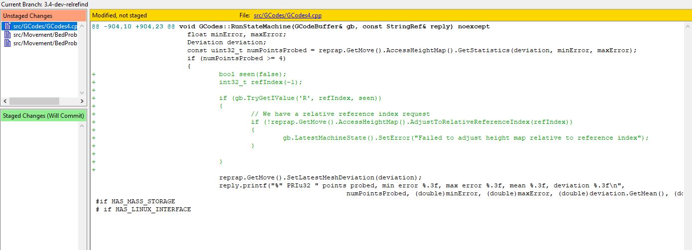
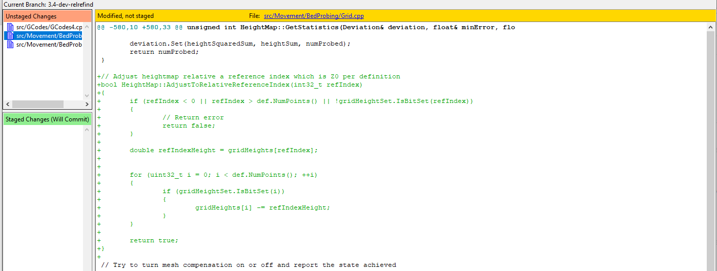
I have now adjusted the firmware for a first try.
I'm probably doing this at the wrong places and some should be moved elsewhere. The reading and the validation of the parameters for example:

and:

So that now, I can do this:

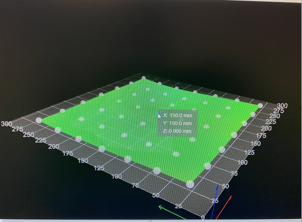
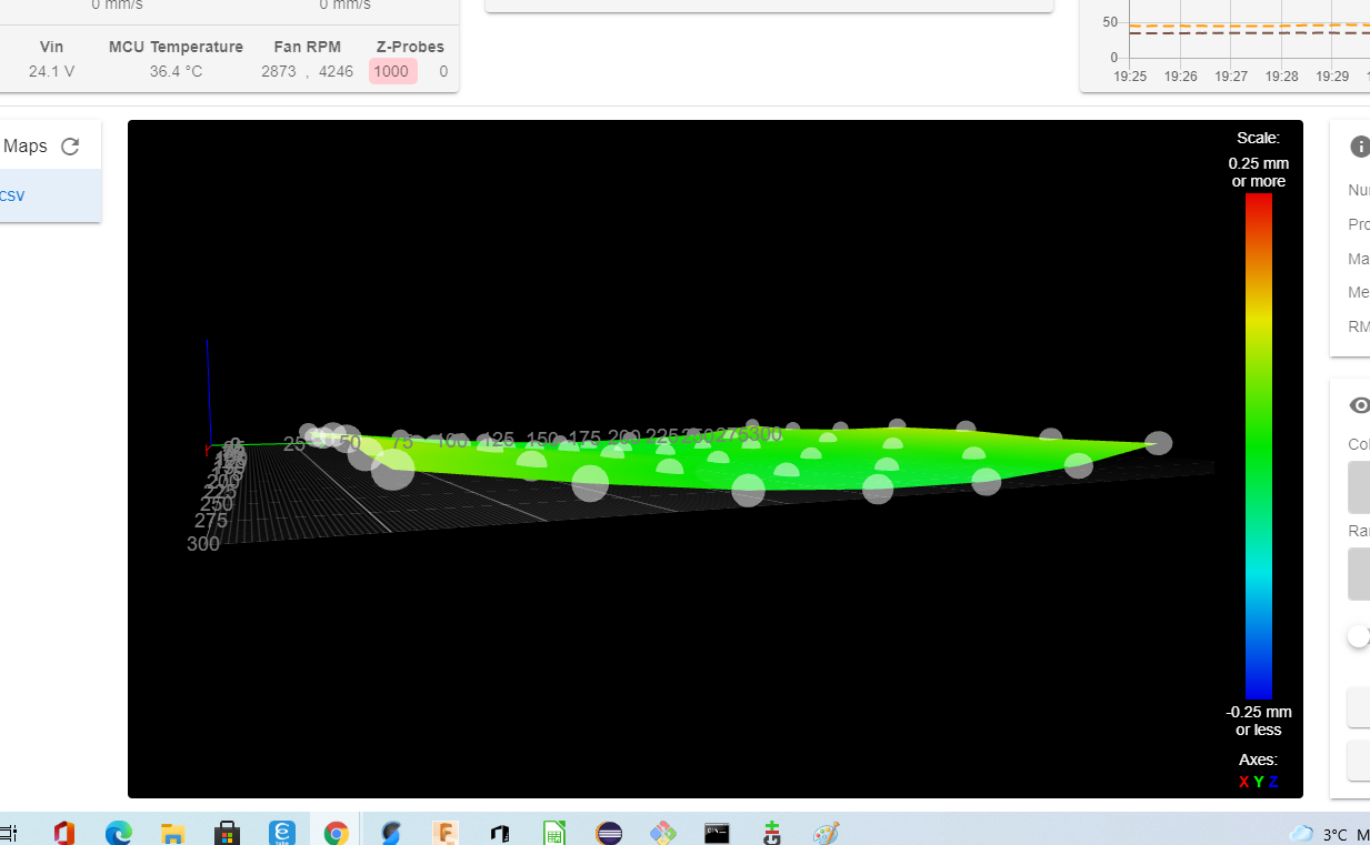
And it results in a mesh (which is cold now, so not much deviation at all but anyway) not dependent on probe offset at all:

Where probe point #24 (zero based) is zero.
Now I can apply this (or better a mesh for a warm bed and printer) of course given that I have made sure that point 24 (center of the bed) is at the height i wish.
Which I do with the auto-z calibration macro: https://github.com/gixxerfast/rrf-voron2/tree/master/macros/autoz
-
First print using the modified firmware.
A one layer print ABS 245 C 110 bed 0.2 mm Z and 260 x 260 mm using the bed mesh.

It's not perfect but it's not bad . I'm quite happy. Since it's all automatic and I just start the print and walk away.
Note, this is the underside not the top side.

It's a tad too squished on the outmost of Y edge. Don't know why but that's something for another day.
-
@gixxerfast I don't think you understand what @fcwilt is suggesting:
- Use the inductive etc. probe to generate the mesh using G29
- After loading the height map, use the nozzle contact probe to set the Z=0 level using G30.
So you need to specify an accurate Z offset for the nozzle contact probe, but not for the inductive probe. No firmware changes are needed, because RRF already supports multiple Z probes.
-
@dc42 Thanks for your reply. Well I might not. But I have checked the code:
The height value that is stored is (or an avergage of):
g30zHeightError = g30zStoppedHeight - zp->GetActualTriggerHeight();
and GetActualTriggerHeight returns -offsets[Z_AXIS]
As far as I can see the offset is stored with the G31
float triggerHeight;
		if (gb.TryGetFValue(axisLetters[Z_AXIS], triggerHeight, seen))
		{
			offsets[Z_AXIS] = -triggerHeight;				// logically, the Z offset of the Z probe is the negative of the trigger height
		}
So the mesh height value that is stored is calculated using the configured probe offset.
Is this not correct?
So if this above is correct, yes you can set the Z0 whichever way you want but you will be dependent on the triggerHeight value that's configured with the G31.
Using the process I have described I'm not.
What have I missed?
/U
-
@gixxerfast said in Mesh probing with Relative Reference Index:
What have I missed?
That a G30 command will prove the bed and set the Z origin accordingly, in effect moving the entire mesh up or down. Maybe you have also missed that you can use one Z probe to generate the mesh and another one to set the Z=0 origin.
-
@dc42 I apologize if my questions seem stupid but my intentions are only to understand how to get it to work as I want.
I have now done some more testing and ...
... Yes, I have misunderstood the term of setting Z0 with the probe as I read that as setting the absolute Z0 position using the probe.
So by issuing the G30 command I set the z coordinate to the probe trigger height (probe offset) and thereby effectively cancelling the probe offset from the rest of the mesh points.
Then it works as I like and I can scrap this whole thread.
My config (that I borrowed starting with RRF a couple of weeks ago) didn't produce a correct mesh since it was obviously configured wrongly and together with a height value that differed a bit from zero probably due to probing inaccuracy led me to believe it worked in a different way than it does.
Well, I learned something new today, it took awhile though

BTW: The -3 flag to the G30 will produce the same result just the other way around, adjusting the probe offset instead of the read height value ?
Thanks
/U -
@gixxerfast said in (EDIT) Already supported in RRF - Mesh probing with Rel Ref Ind:
BTW: The -3 flag to the G30 will produce the same result just the other way around, adjusting the probe offset instead of the read height value ?
Yes, G30 S-1 will adjust the trigger height to match the current Z instead f the other way round.
Use the K parameter on the G30 and G29 commands to select which Z probe to use for each command.