Setting up Accelerometer and wiring
-
@ccs86 yes that is the typical error. The CS pin must come first.
Duet WiFi hardware designer and firmware engineer
Please do not ask me for Duet support via PM or email, use the forum
http://www.escher3d.com, https://miscsolutions.wordpress.com -
@dc42 Could check my diagram?
-
@reczul-01 Looks good to me. If you use a ribbon cable, you may have to connect a 1k resistor in series with SDO/MISO at the accelerometer end - that's what I had to do to get mine working.
-
@chrishamm thanks
-
@chrishamm I have a small problem (I did solder resistors to filter out noise) I cannot connect to accelerometer
-
@reczul-01
M955 P0 C"io3.out+io3.in"should be OK with the diagram you posted before. How long is the cable and did you check continuity on every wire? You could also try to reduce the clock speed initially by sendingM955 P0 C"io3.out+io3.in" Q500000instead.Duet software engineer
-
@chrishamm said in Setting up Accelerometer and wiring:
M955 P0 C"io3.out+io3.in" Q500000
Unfortunately non those commands work, I did check continuity but in a second I will do it again
-
@chrishamm said in Setting up Accelerometer and wiring:
M955 P0 C"io3.out+io3.in"
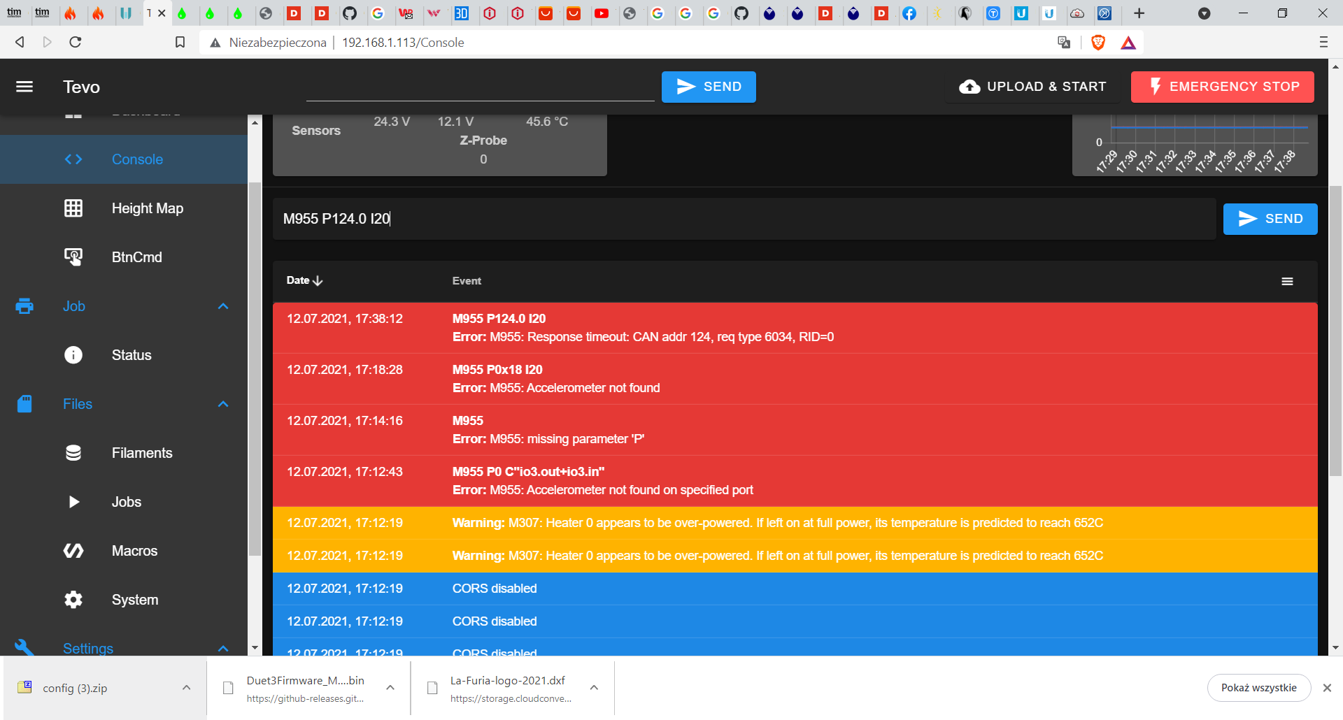
I managed to remake connections and now it works, beside collecting data
-
@reczul-01 use M956 P0 instead of P124.0. I'll investigate the error message you got.
Duet software engineer
-
@chrishamm same message
-
@chrishamm If you would like I can give you remote acces to my printer
-
@reczul-01 Reset your printer once and try again. I won't have a chance to look at it before tomorrow.
-
@chrishamm ok
-
@dc42 said in Setting up Accelerometer and wiring:
yes that is the typical error. The CS pin must come first.
exp.pa21 = EXP_0
exp.pa22 = EXP_1Right?
-
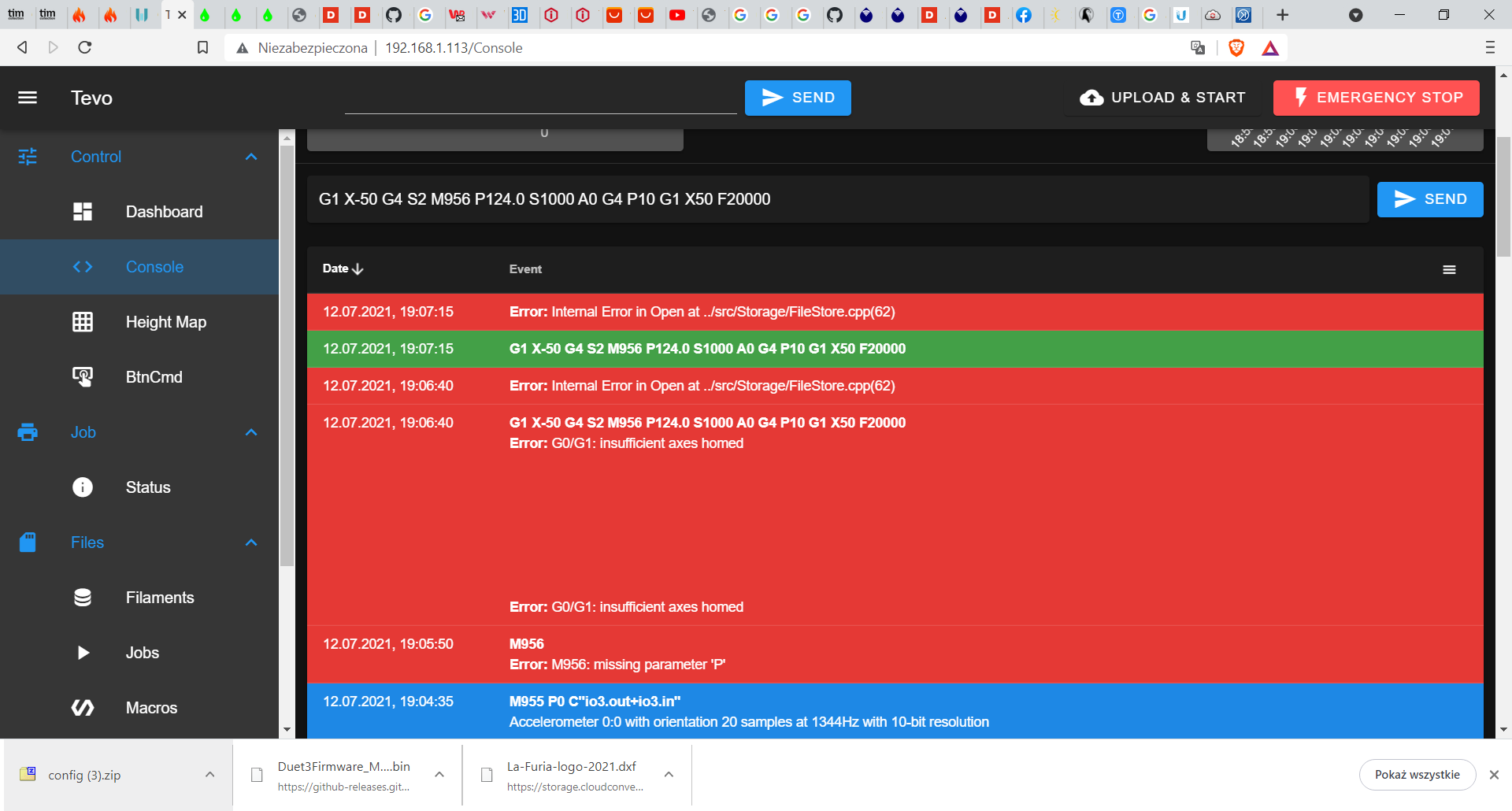
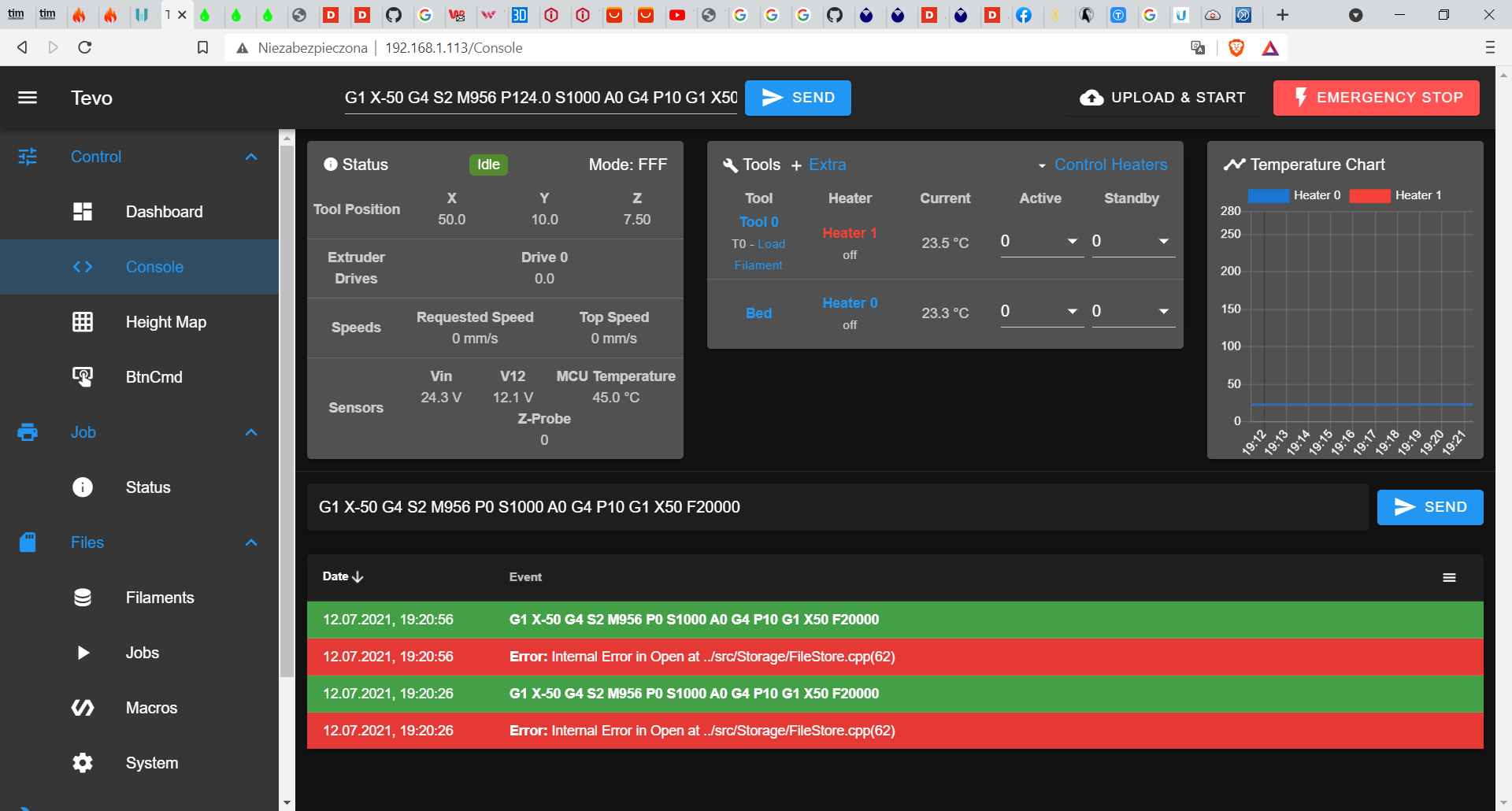
@reczul-01 You must be on v3.4-b1 from the unstable package feed in order to use accelerometers in SBC mode. Your error message indicates that you are still running RRF 3.3 which does not support file operations on the SBC.
@CCS86 Yes, that's right.
-
@bot said in Setting up Accelerometer and wiring:
@dc42 I've had a theory for a while that the thin heatbreak of the common E3D V6 moves a lot during printing. Perhaps it would be beneficial to mount the accelerometer directly to the (cold) heat block?
See this rudimentary analysis of resonant frequencies I did:
Probably it would be useful to design a bracket that mounts the sensorboard on the (cold) heaterblock? It's meant to be a temporary installation anyway until you've dialed in the input shaper.
-
@ccs86 said in Setting up Accelerometer and wiring:
@dc42 said in Setting up Accelerometer and wiring:
yes that is the typical error. The CS pin must come first.
exp.pa21 = EXP_0
exp.pa22 = EXP_1Right?
You can also try using the TWC0 and TWD0 pins instead of EXP0 and EXP1.
Duet WiFi hardware designer and firmware engineer
Please do not ask me for Duet support via PM or email, use the forum
http://www.escher3d.com, https://miscsolutions.wordpress.com -
When using twisted pair cable, which wires would be most important to keep further apart?
-
@o_lampe I suppose it wouldn't hurt to do that. However, as dc42 pointed out, and I seem to have confirmed by doing a few more very rudimentary FEA tests, the frequency that is excited with the geometry of the hot end is quite high.
I think other users have done tests and experiments that show that these ringing frequencies originate in the belts and motors. The frame and other components are not likely vibrating excessively at the low frequencies that we see in ringing.
-
@bot
I didn't mean that the heatsink/hotend add to the equation, but the long lever of the heatsink amplifies the amplitude which makes it easier to separate resonance from noise.
And it would be easier to design a universal bracket, since most heatblocks share more or less the same dimensions. While brackets for carriers are often one_of_a_kind.