Setting up Accelerometer and wiring
-
@mikes said in Setting up Accelerometer and wiring:
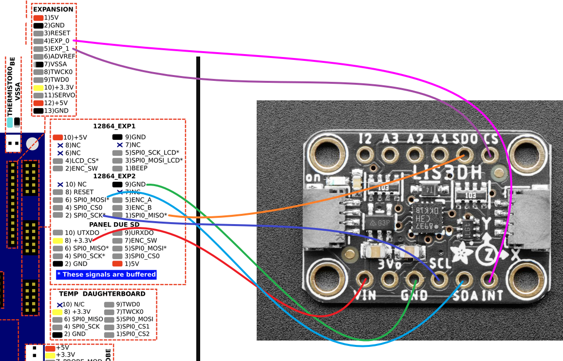
@ccs86 12864 SPI0_CS0 and PANEL DUE SD SPI0_CS0 seems to be sharing the same CPU pin. I would connect INT of the accelerometer to TEMP DAUGHTERBOARD SPI0_CS1 or SPI0_CS2. I'm not sure at all because i have a 2wifi and not a maestro.
That wire was my least confident one. Unfortunately, I am using the temp daughterboard for my PT100 bed sensor... unless that pin is unaffected and I can just grab it on the output pins of the daughterboard.
-
@ccs86 Give it a try but i think it won't work cause the MAX31865 chip should be powered and connected to these pins.
Fast solution is to cut the trace on the daughterboard (if not used) that connect cs2 to the chip and solder the INT pin there.
Cleaner one is to create an extension cable that expose that pin for the accelerometer and route all other pins to the daughterboard.
In any case you should wait someone more experienced than me on that board...maybe some other pins can be used. -
@ccs86 I suggest you connect the CS and INT pins to pins EXP_0 and EXP_1 on the expansion header. In the M955 command, refer to them as "exp.pa21+exp.pa22".
Duet WiFi hardware designer and firmware engineer
Please do not ask me for Duet support via PM or email, use the forum
http://www.escher3d.com, https://miscsolutions.wordpress.com -
@dc42 said in Setting up Accelerometer and wiring:
@ccs86 I suggest you connect the CS and INT pins to pins EXP_0 and EXP_1 on the expansion header. In the M955 command, refer to them as "exp.pa21+exp.pa22".
Thank you!
Revised at your suggestion:
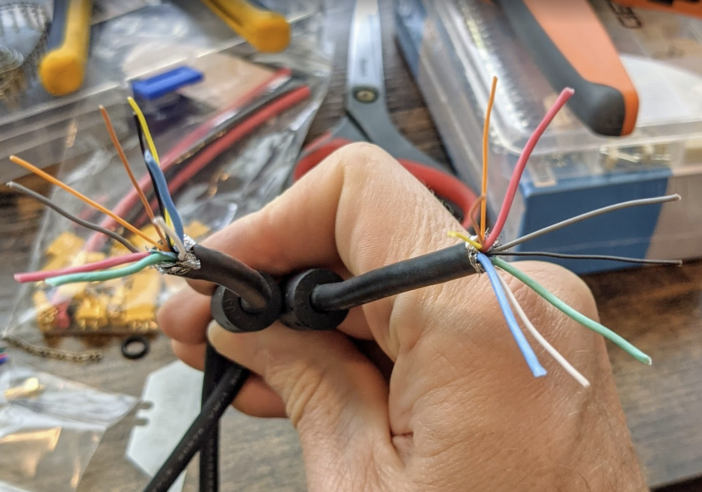
I know that some people have struggled with the wiring itself. Have any best practices been established yet? I was originally going to use ethernet cable, but saw people struggling with that. Some said USB 3.0 cable, but that only has 4 conductors. I was thinking about using this VGA cable:
-
@dc42 said in Setting up Accelerometer and wiring:
@bot I suspect that any resonance of the hot end heater block would be at a somewhat higher frequency than the usual troublesome resonances in 3D printers, because the heater block has quite low mass if it's an aluminium one, and the heat break is quite stiff. But by all means, see if you can measure it.
@dc42 That's a good point. For example, in that very GIF I posted, the resonant frequency identified is above 50 kHz (edit: seems to say ~5 kHz, not 50. The photo was blurry)! It might be worth experimenting with, but it seems like (again) you are correct!
Edit: Yeah, I just checked the simulation and the lowest identified harmonic frequency is 1770 Hz. Much higher than important, no? Frequencies that the shaper will deal with are in the order of 50 hz or less, right?
-
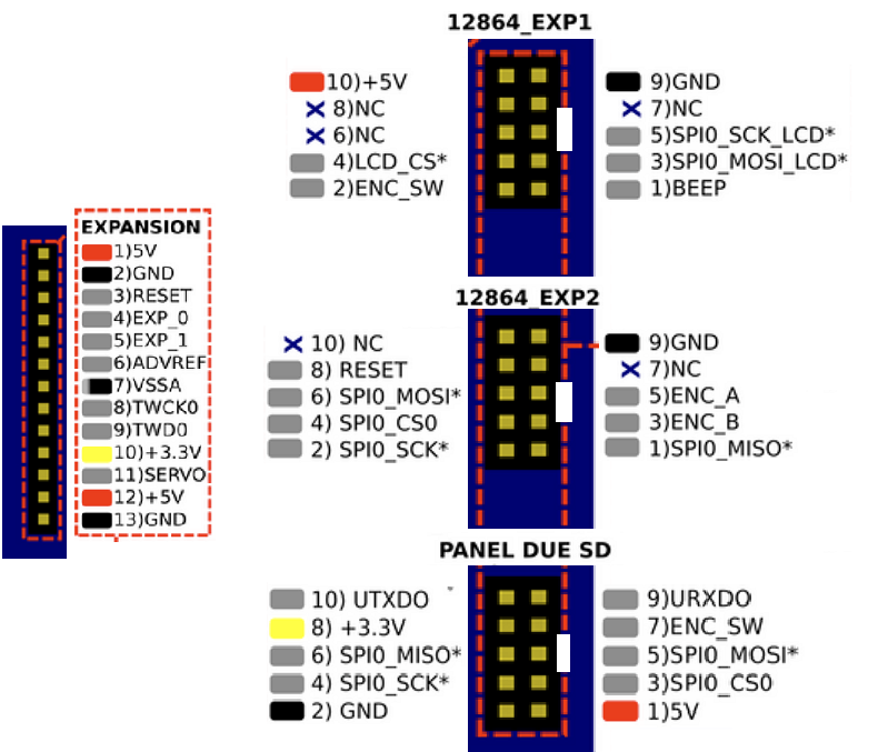
One more question: Am I interpreting the Maestro pinout diagram correctly?
-
@ccs86 yes your wiring diagram looks OK to me.
Re wiring, I now recommend using a 1K resistor in series with the SDO signal at the accelerometer board end.
On my delta I use an unshielded 8-core cable to connect the accelerometer, and it works even without the resistor. I think that VGA cable should be OK.
Duet WiFi hardware designer and firmware engineer
Please do not ask me for Duet support via PM or email, use the forum
http://www.escher3d.com, https://miscsolutions.wordpress.com -
@dc42 said in Setting up Accelerometer and wiring:
@ccs86 yes your wiring diagram looks OK to me.
Re wiring, I now recommend using a 1K resistor in series with the SDO signal at the accelerometer board end.
On my delta I use an unshielded 8-core cable to connect the accelerometer, and it works even without the resistor. I think that VGA cable should be OK.
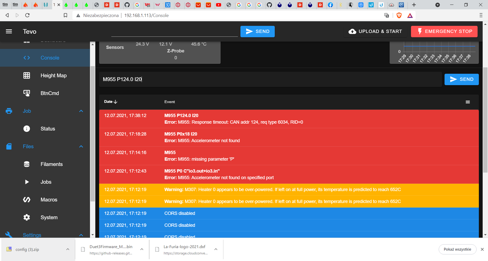
Is the typical error without that resistor "accelerometer not found"? (edit: 1k resistor inline on SDO and still getting accelerometer not found)
When defining the accelerometer with M955 P0 C"[first pin]+[second pin]", are you defining CS in the first pin and INT in the second pin? Or does the order even matter?
-
Can somebody help me with wiring diagram to connecting the same acclolmeter as one above to duet 3 6hc 1.01.
-
-
@ccs86 yes that is the typical error. The CS pin must come first.
Duet WiFi hardware designer and firmware engineer
Please do not ask me for Duet support via PM or email, use the forum
http://www.escher3d.com, https://miscsolutions.wordpress.com -
@dc42 Could check my diagram?
-
@reczul-01 Looks good to me. If you use a ribbon cable, you may have to connect a 1k resistor in series with SDO/MISO at the accelerometer end - that's what I had to do to get mine working.
-
@chrishamm thanks
-
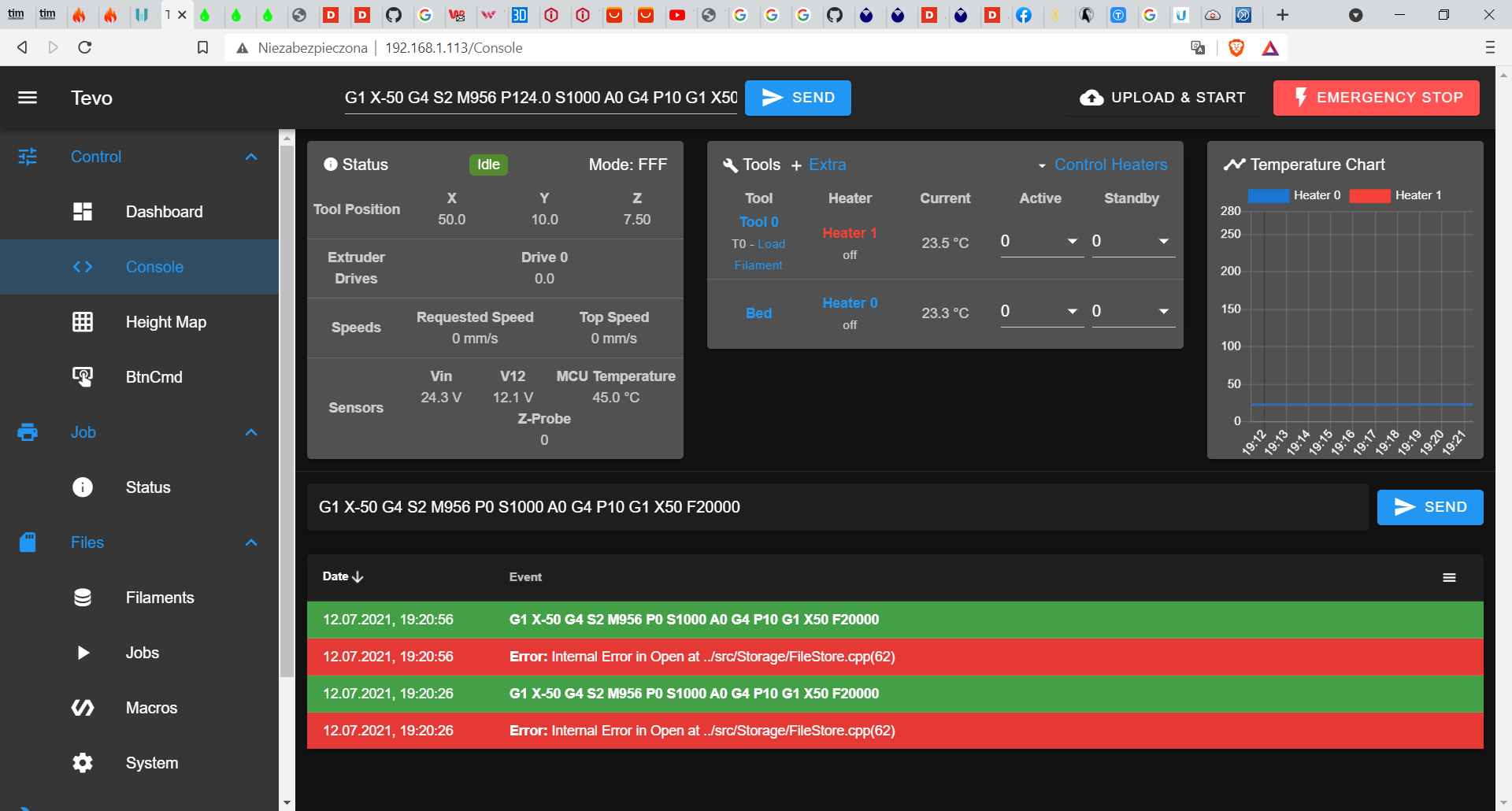
@chrishamm I have a small problem (I did solder resistors to filter out noise) I cannot connect to accelerometer
-
@reczul-01
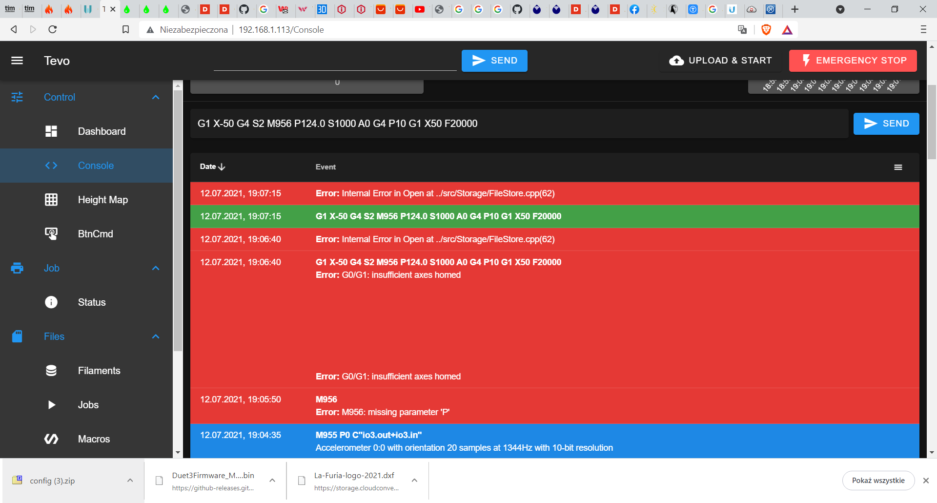
M955 P0 C"io3.out+io3.in"should be OK with the diagram you posted before. How long is the cable and did you check continuity on every wire? You could also try to reduce the clock speed initially by sendingM955 P0 C"io3.out+io3.in" Q500000instead.Duet software engineer
-
@chrishamm said in Setting up Accelerometer and wiring:
M955 P0 C"io3.out+io3.in" Q500000
Unfortunately non those commands work, I did check continuity but in a second I will do it again
-
@chrishamm said in Setting up Accelerometer and wiring:
M955 P0 C"io3.out+io3.in"
I managed to remake connections and now it works, beside collecting data
-
@reczul-01 use M956 P0 instead of P124.0. I'll investigate the error message you got.
Duet software engineer
-
@chrishamm same message