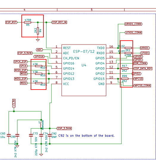
ethernet to esp breakboard
-
@apak that's great thanks.
Will the surface mount headers idea still allow the ethernet module to fit if required?
-
@cncmodeller sure, why not?
-
@apak said in ethernet to esp breakboard:
@cncmodeller sure, why not?
I only ask as the ethernet headers on my Duet are 1/height.
-
@apak said in ethernet to esp breakboard:
Do you think that I could get any trouble using this board?
It will almost certainly generate more EMI than the on-board WiFi module, so getting CE certification for a printer using it might be difficult. Other than that, I don't see any problems. The critical traces to keep short are the ground traces and the SPI traces.
-
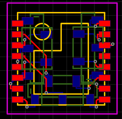
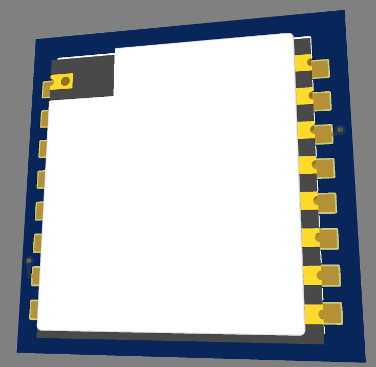
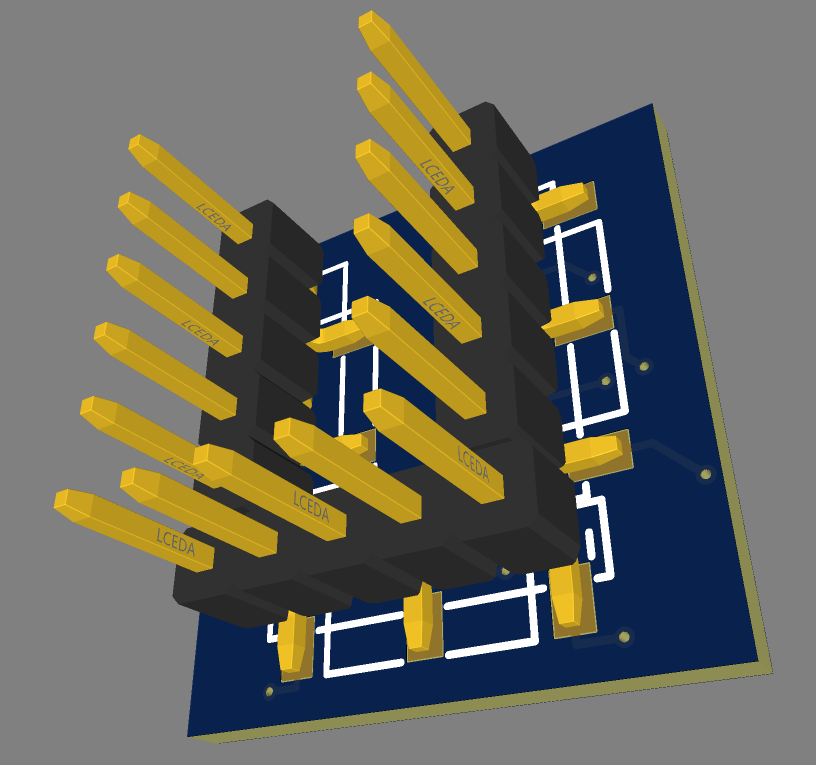
@dc42 in that case I will try this breakboard, shorter pads
-
@apak
The positions of some 'vias' are pretty close to adjacent pads. The routing could use some cleaning... -
@o_lampe I have no tecnical education, I used the autoroute feature. Already ordered.
First pcb disconnects from wifi once you start to print....so DON´T use first PCB
-
@apak have you included any resistors that may be required?
-
@jay_s_uk nope
-
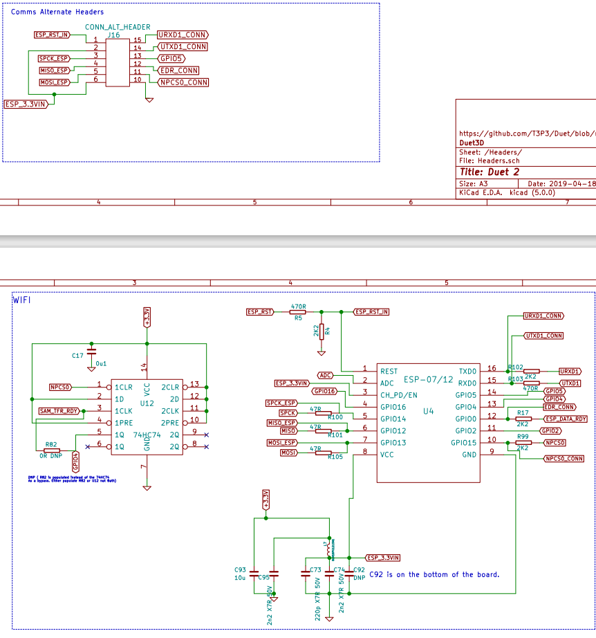
@apak i suggest you review the schematics.
I don't know what resistors aren't included onboard when its the ethernet module and some may be required to be added on certain lines. -
@jay_s_uk don´t see any, looks like direct pin contact between "comm alternate header" and ESP pins
-
-
The other thing that may be missing on an Ethernet board is the 74HC74 chip. However, if you use wifi firmware 1.24 or later then you can bypass it by installing R82.
-
@jay_s_uk all that should be already on the duet board, we are talking to direct pin contact between alt comm ports and the esp solder traces...
At this point I point out that I have just converted ethernet clone boards to esp-07s so far with no trouble, but soldering the esp to the board traces
-
@apak fair enough. It's just not what the schematics implies
-
@apak
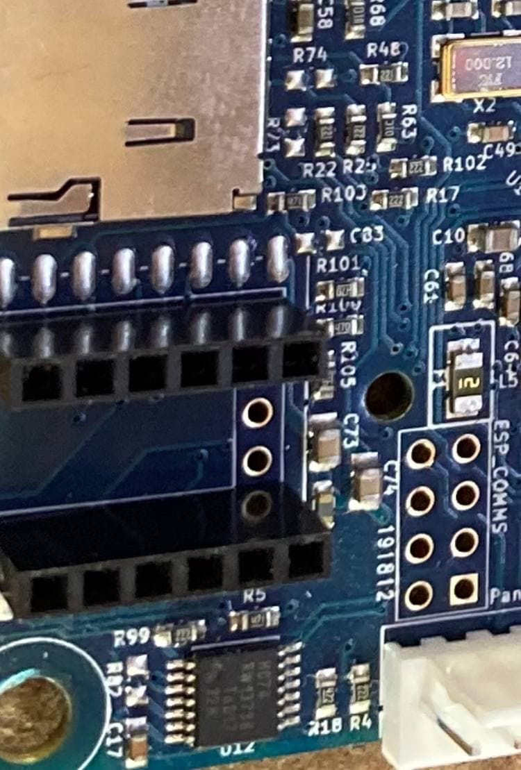
seems everything is in place, also the 74HC74guess that the chinnese clons just install everything for the wifi version and then just plug the ethernet board
-
@alankilian said in ethernet to esp breakboard:
@apak If you ever want to do this kind of thing again, you might want to use these surface-mount 0.1" header pins.
https://www.digikey.com/en/products/detail/oupiin/2015-1X40G01DBB/13251225pay attention that these are not super strong and that, especially with 3 raw's of pins, removing the board from the socket requires a lot of force and it can rip the pins off the board ... happened to me too many times to count
 that I avoid using the smd .1" pins any time I can
taking into account how free the boards at jlcpcb are I'd go with 4 layer, put all the traces inside and ground on the outside, it should help with EMI and the behavior of the ESP module and would not change the price of the board significantly
-
@arhi
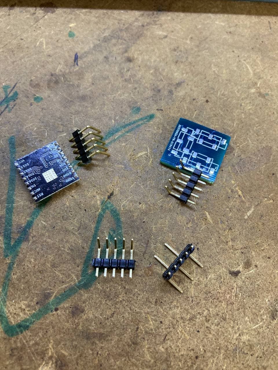
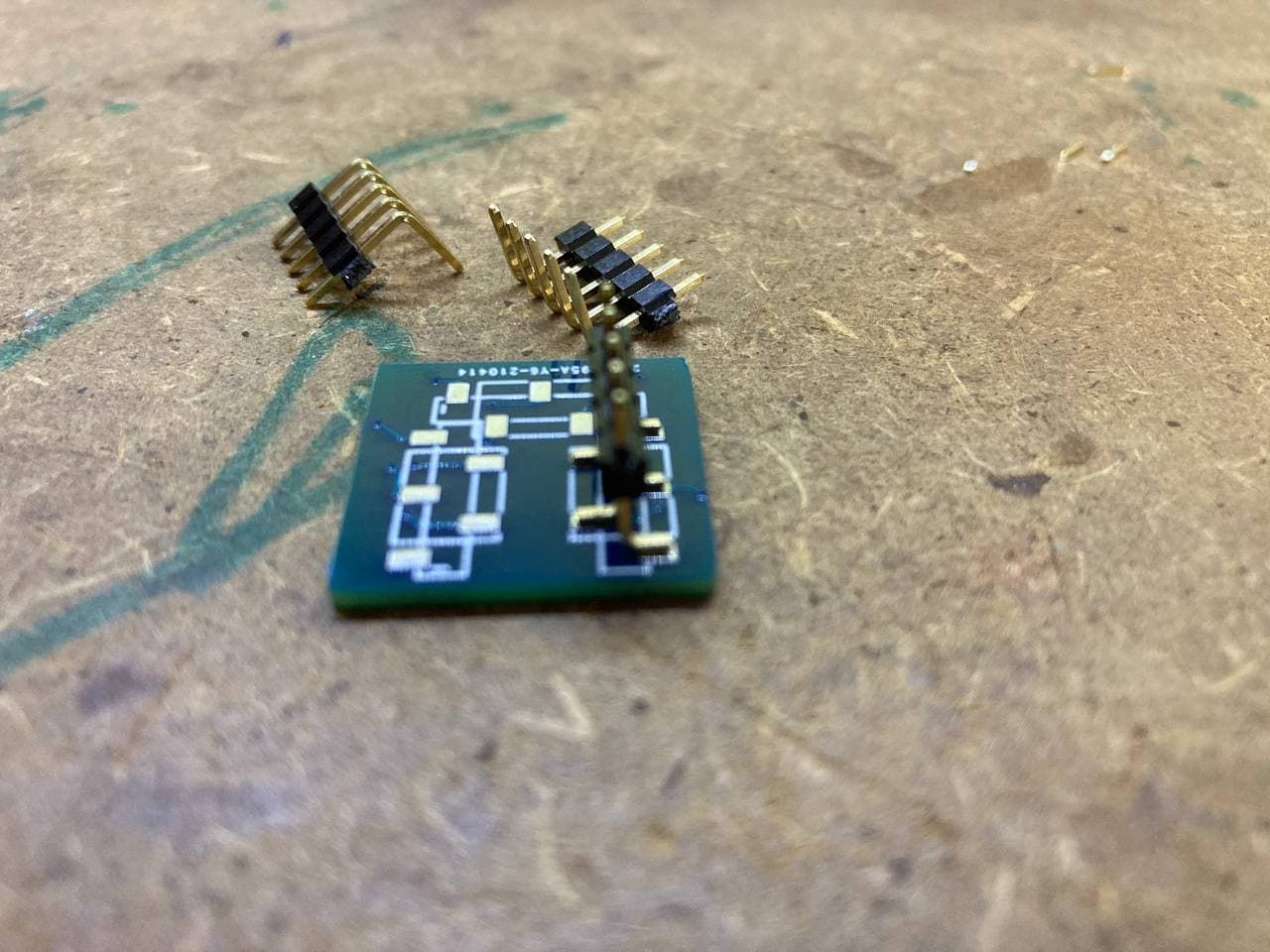
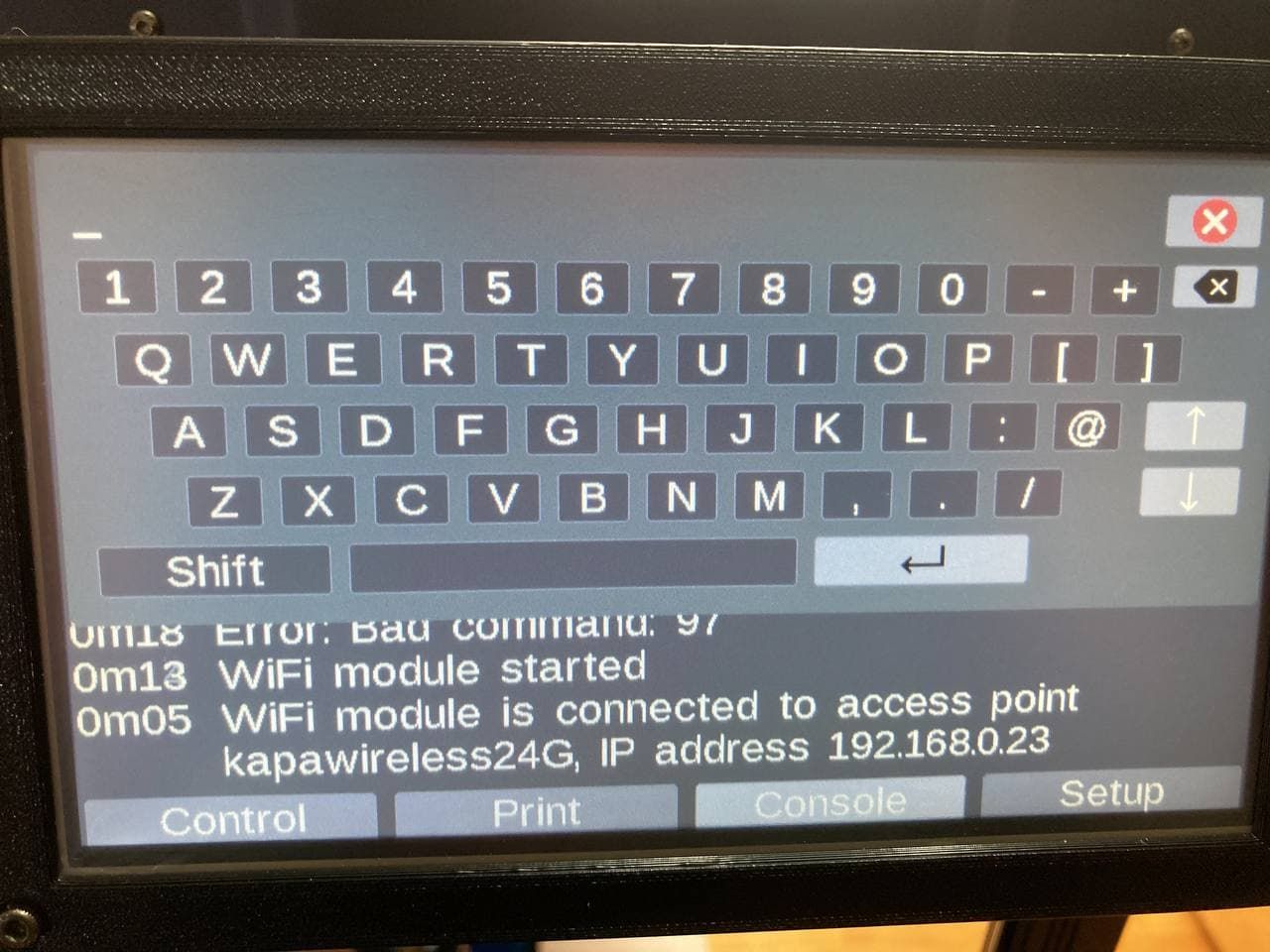
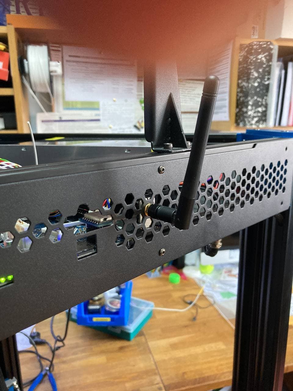
I had to make my own pin strip since on my local store didn´t have themIt´s working fine, no disconnections while printing like with the first prototype
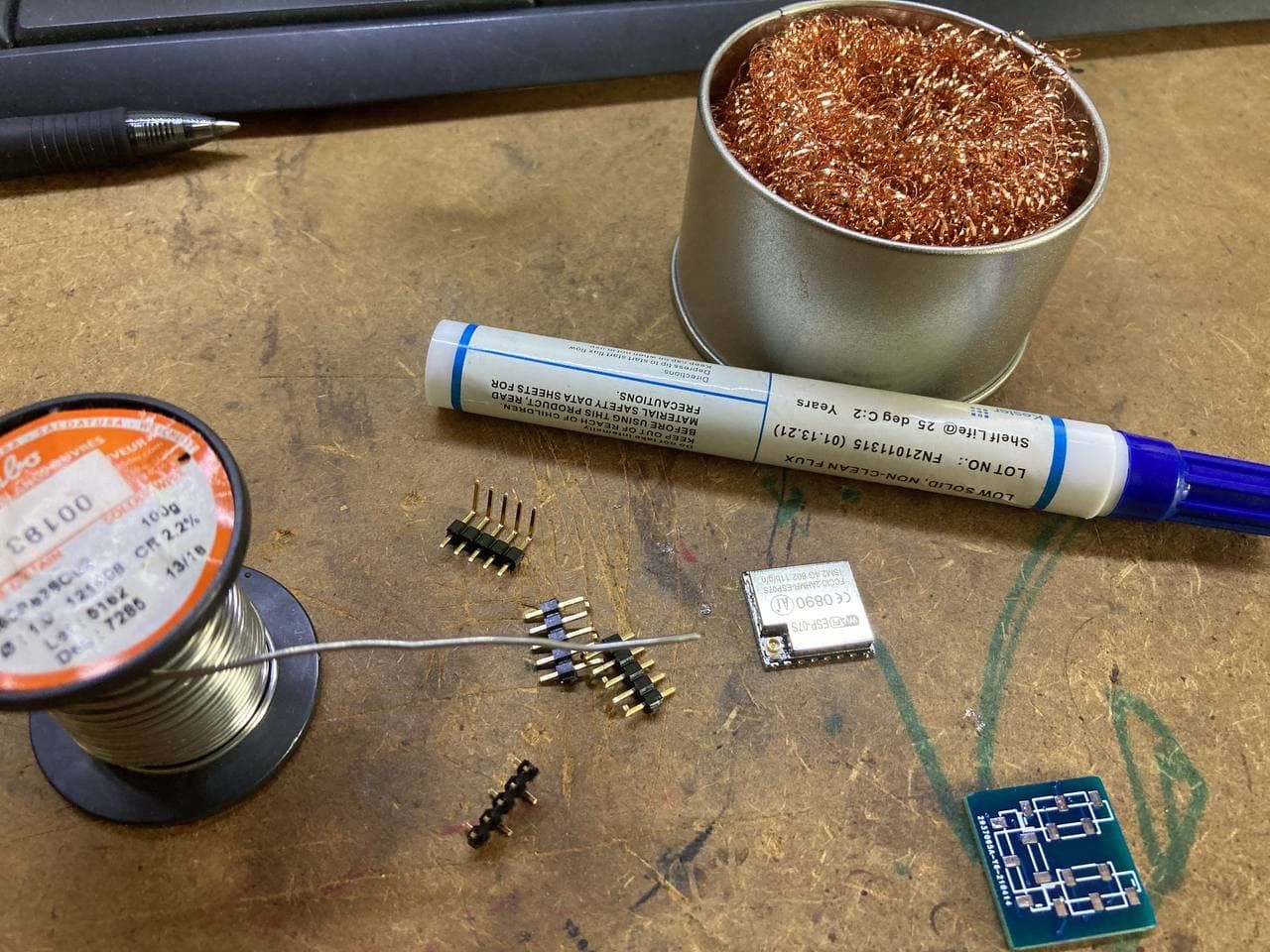
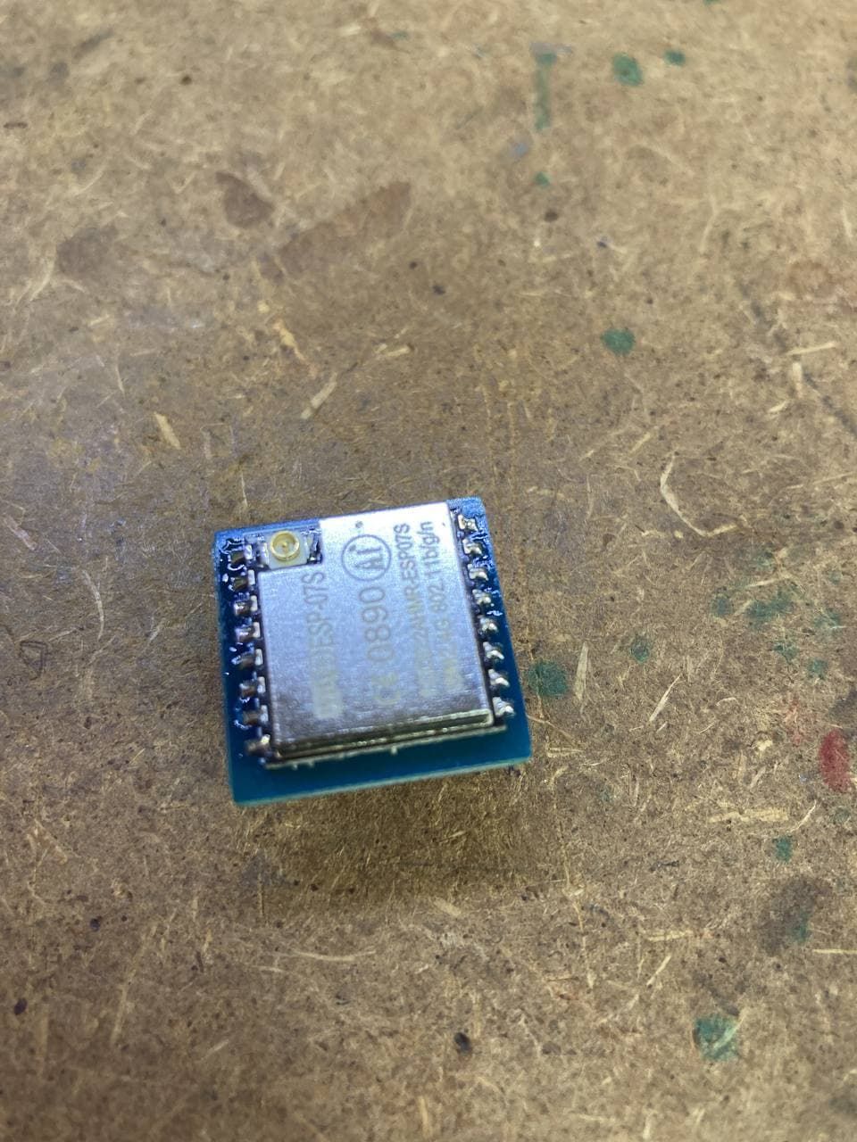
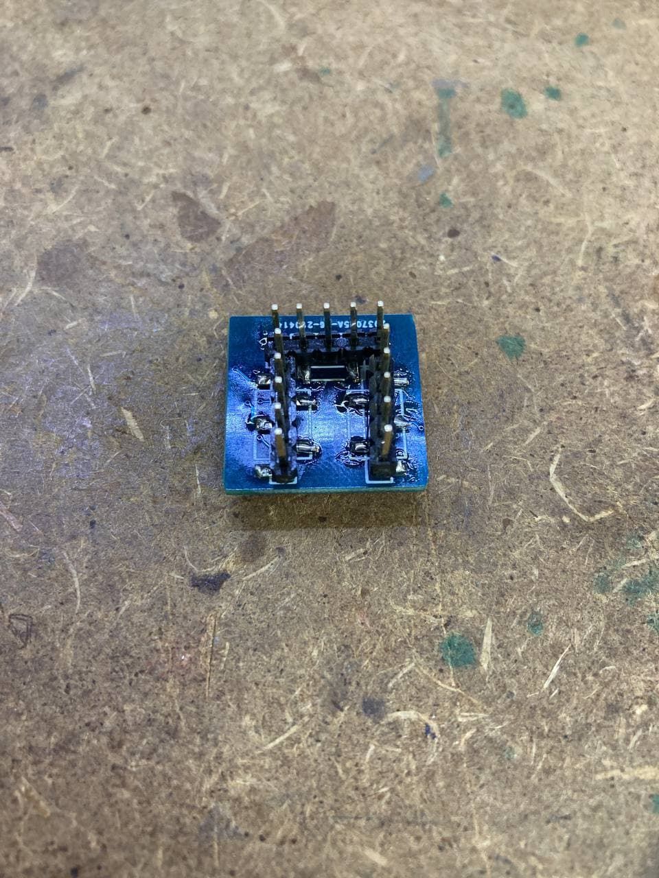
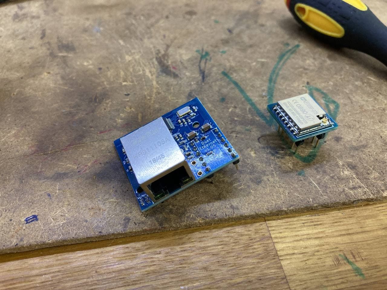
-
@apak said in ethernet to esp breakboard:
no disconnections while printing like with the first prototype
I have never seen those disconnect from vibrations, I had them rip out the pads when you try to remove them from the header
-
@arhi I meant the the first prototype had wifi disconections due to long tracks, this one has shorter pads, and looks like it works just fine while printing. The first one just didn´t work while printing
