Duet 3 Tool Board
-
I`m going to use Duet3 + ToolBoard
Then I have to get a RJ11 cable (the cable kit includethe other wires I need?)
Add a 5A (car fuse) for the power wires
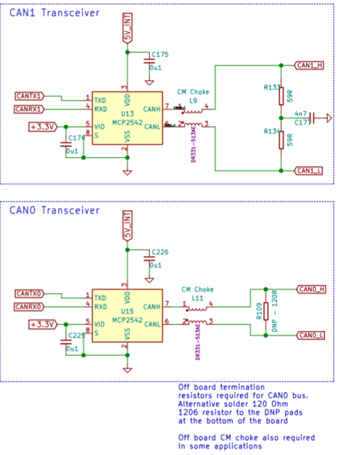
Terminate the CanBus using a 120 Ohm resistor? where? between pin 3-4? -
@mundsen said in Duet 3 Tool Board:
Terminate the CanBus using a 120 Ohm resistor? where? between pin 3-4?
Yes, between pins 3-4 of the 4-pin CAN connector on the Tool Board.
-
Is there a better picture of the connector pack available ?
-
@dc42 all 4 wires from duet 3 connected or only 1 and 2
-
@mundsen said in Duet 3 Tool Board:
@dc42 all 4 wires from duet 3 connected or only 1 and 2
does this answer the question?
https://raw.githubusercontent.com/Duet3D/Hardware/master/Duet3/Duet3_MB6HC_schematic_v1.0.pdf

-
@mundsen said in Duet 3 Tool Board:
@dc42 all 4 wires from duet 3 connected or only 1 and 2
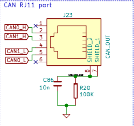
If using one tool board: connect pins 3 and 4 (the middle 2 pins) of the RJ11 connector on the Duet to pins 4 and 3 of the tool board, making sure you get them the right way round i.e. CAN1_H in the Duet to CANH on the tool board, and connect a 120R termination resistor between pins 1 and 2 of the connector on the tool board. [Pins 2 and 4 of the tool board are interchangable, as are pins 1 and 3.] Don't connect anything to pins 2 and 5 of the RJ11 connector on the Duet.
To clarify this, I've uploaded the tool breakout (distribution) board schematic to:
https://github.com/Duet3D/Duet3-Tool-Distribution-Board/tree/master/Tool Distribution v0.5(edited by T3P3Tony to point to new locations for Duet 3 Schematics)
-
If using one tool board: connect pins 3 and 4 (the middle 2 pins) of the RJ11 connector on the Duet to pins 4 and 3 of the tool board, making sure you get them the right way round i.e. CAN1_H in the Duet to CANH on the tool board, and connect a 120R termination resistor between pins 1 and 2 of the connector on the tool board. [Pins 2 and 4 of the tool board are interchangable, as are pins 1 and 3.] Don't connect anything to pins 2 and 5 of the RJ11 connector on the Duet.
To clarify this, I've uploaded the tool breakout (distribution) board schematic to https://github.com/Duet3D/Hardware/tree/master/Duet3.
And in case anyone is wondering why a resistor is required. have a read of the following link Terminal Resistor
-
@CaLviNx I originally read you "wondering why... " as just "why...". You linked to a good source!
I'll add this thought to re-enforce the potential effects!
The resistors stop reflections at the end(s) of the cable. Often, on short cables, the bus will seem to run OK without them.
However... Suppose your printer works great, and unknown to you is right on the edge of signal reflection corrupting the CAN bus. Then days or even months down the road, the temperature/humidity changes, or the connection changes (maybe it gets better)... and, bang, the printer starts acting completely flakey and unreliable.
-
Anyone old enough to remember SCSI hard disk? They had a SIP resistor pack in the last drive on the 50w ribbon cable.
-
@tekkydave More than old enough lol and still work on kit that use SCSI Buses so well aware of bus terminations
-
@tekkydave said in Duet 3 Tool Board:
Anyone old enough to remember SCSI hard disk? They had a SIP resistor pack in the last drive on the 50w ribbon cable.
I must be old, I remember the IDE drives and even 5 1/4" floppies...

But I never used the big 8" stuff...


-
@timcurtis67 you never worked PDP11's then? Mind I can go back even further to the times of an IBM 1130 which used EBCDIC punched cards or a frantic Argos 500 with handlers and punched tape.
-

Anyone having the stp files for the 3 and 4 pin JST ZH + the 6 pin (stepper output) + the button?
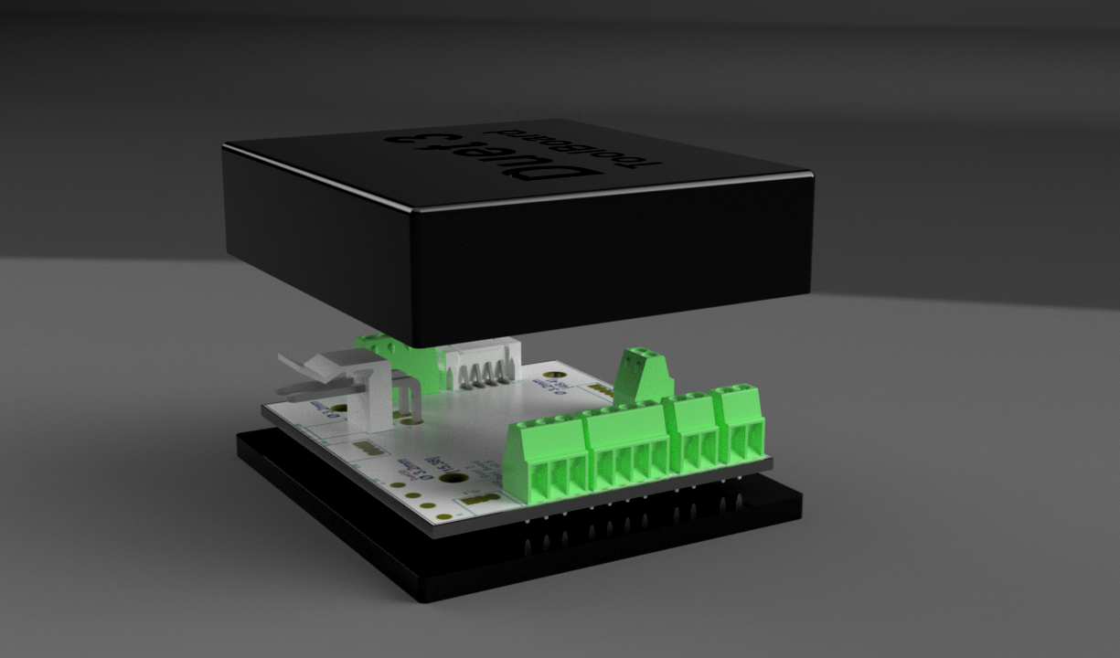
I`m making a simple (not 100% accurate) ToolBoard 3D model that I can use in my designs + when designing a housing for it
-
@timcurtis67 said in Duet 3 Tool Board:
@tekkydave said in Duet 3 Tool Board:
Anyone old enough to remember SCSI hard disk? They had a SIP resistor pack in the last drive on the 50w ribbon cable.
I must be old, I remember the IDE drives and even 5 1/4" floppies...

But I never used the big 8" stuff...


I did! [Cue "You were lucky!" spoken with a Yorkshire accent].
I also remember when we asked one of our customers for a copy of their backup disks (this was before email) so we could diagnose the issue they reported. Next day it arrived by post... a perfect photocopy of a pair of 8" floppy disks!
-
@dc42 said in Duet 3 Tool Board:
a perfect photocopy of a pair of 8" floppy disks!
A page with pixels and a 8"" floppy represent about the same number of bits.

Seriously, I may missed it, what are the dimension of this board?
-
@zapta said in Duet 3 Tool Board:
Seriously, I may missed it, what are the dimension of this board?
As shown at https://duet3d.dozuki.com/Wiki/Duet_3_Tool_Board.
-
@dc42 https://www.dropbox.com/s/eh33zxsda53bvhv/2020-02-21 13.56.06.jpg?dl=0 look familiar?
https://www.dropbox.com/s/oamu8uhdz134qj6/2020-02-21 13.55.32.jpg?dl=0 from our antique computing pile at work
-
@daavery said in Duet 3 Tool Board:
@dc42 https://www.dropbox.com/s/eh33zxsda53bvhv/2020-02-21 13.56.06.jpg?dl=0 look familiar?
https://www.dropbox.com/s/oamu8uhdz134qj6/2020-02-21 13.55.32.jpg?dl=0 from our antique computing pile at work
Double sided 8 inch floppy? Luxury!
-
@dc42 double sided double density 1.2M
-
@dc42 Although I don't see a statement to the effect, I'm assuming IO0 is meant for the Z probe and IO1 the filament sensor yeah? Can IO1 be used as an X endstop instead?