G29 Vs G32
-
my suggestion is to start of with the basics.
forget about the dual extruder for now and just focus on the first extruder.
your offset from the nozzle is quite large.
if after a g29 your print is higher on one side than on the other that suggests that the z offset changes with the position of the printhead.
this could be due to tilting or other imperfections.
you still have not posted anything about the repeatability of your probe.so post a picture of a detailed g29.
and indicate across the picture where the print is in the air and where it is ok and where it is squashed. -
Results of repeatability test:
M98 P"0:/macros/BlTouch/Repeatability test"
G32 bed probe heights: -0.190 -0.188 -0.185 -0.197 -0.195 -0.197 -0.195 -0.195 -0.195 -0.197, mean -0.194, deviation from mean 0.004
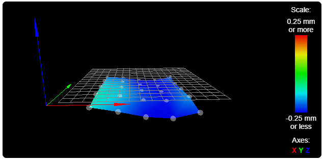
G29 25 point probed:
G29
Warning: the height map has a substantial Z offset. Suggest use Z-probe to establish Z=0 datum, then re-probe the mesh.
25 points probed, min error -0.303, max error -0.100, mean -0.201, deviation 0.053
First layer of test print includes G29 as above:

First layer of test print WITHOUT G29:

-
Further to the above this is the completed print with mesh bed compensation:

Compared to this, without mesh bed compensation:

Clearly for some reason the mesh bed compensation is working against me, any help appreciated.
-
@lyndon said in G29 Vs G32:
G29
Warning: the height map has a substantial Z offset. Suggest use Z-probe to establish Z=0 datum, then re-probe the mesh.you have a big difference from when you are homing to when you are probing.
can you remove T-1 from your homeall. and try again.
also please post your config-overwrite.g -
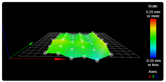
Hi, I have remove T-1 from homeall.g and here is the Latest G29:
25 points probed, min error -0.072, max error 0.152, mean 0.034, deviation 0.067Contents of config-overide.g:
; config-override.g file generated in response to M500 at 2019-12-27 09:42
; This is a system-generated file - do not edit
; Heater model parameters
M307 H0 A36.2 C173.9 D2.8 S1.00 V11.6 B0
M307 H1 A468.5 C177.5 D9.8 S1.00 V12.1 B0
M307 H2 A434.1 C167.6 D6.7 S1.00 V12.1 B0
Going to re run that test print now..
-
@lyndon said in G29 Vs G32:
Going to re run that test print now..
before you do recheck your offset.
please measure exactly and confirm that the offset for the first nozzle ist
X-21 Y50
use a ruler below the nozzle and take a picture both in the y and x direction.then set the probing distance between points to something very small. i.e. 15mm and then try printing again.
-
Sorry mate print already started before I read your reply.
I have re measured the probe offset and it's actually X-45 and Y55. I have corrected these in config.g. As you can see from the tool head photos, it's not the easiest measurements to take. So I marked paper on the bed the position of the nozzle and probe, hope it makes sense.
Image showing probe left of nozzle:

Image showing probe behind nozzle:

Measurements of probe offset:

New height map 42 points probed:

Console output of G29:
42 points probed, min error -0.123, max error 0.110, mean 0.012, deviation 0.054
Height map saved to file heightmap.csv
And here is the finished print for the above changes:

-
your bed seems very uneven.
from your config i can see that your bed is about 250mm.
but i can see only 6 points. thats is 1 point every 40mm given the irregularities of your bed, that is not enough.when you updated your offset, did you remember to account for your offset that you configured in the tool config?
-
Hi the bed is 300 x 300 but due to the large head the printable area is about 250 yes.
But the bed is NOT as bad as the G29 mesh is saying. Hence the print I did without using mesh bed compensation. However it is pot luck what area of the bed I print on, ie. different model sizes. So I would prefer to use mesh bed comp.
Oh yes I didn't take the tool offset into account, should I subtract that from the probe offest or add it ?
Also I have just updated firmware to 2.05 after reading this:
Bed compensation did not take account of the XY offset of the printing nozzle from the head reference pointon github. But not had time to play since, I hope to have time later today.
-
@lyndon said in G29 Vs G32:
Oh yes I didn't take the tool offset into account, should I subtract that from the probe offest or add it ?
See this documentation:
https://duet3d.dozuki.com/Wiki/Test_and_calibrate_the_Z_probe#Section_Measuring_Probe_X_Y_Offset
-
that documentation assumes that the tool point is a nozzle.
he defined his x0 y0 to be between his 2 nozzle and is making his life a lot harder that way. -
@veti, I strongly agree with your last post. The "Control Point" from G-Code's perspective needs to be 0,0,0 aligned with ONE of the nozzles. Everything else is an offset from that base.
It is almost essential that he do this, so that all the people trying to help him, and OP himself, are "on the same page".
@lyndon Does this make sense?
-
Hi all. what and idiot I am, I hadn't changed the tool offset since replacing my chimera hot end for this duel switching head. DUH.
with the new head the offset is more like 2mm. So for now I have set tool offset to 0 as suggested, and since the head change I agree.I have now re levelled the bed and am running a detailed G29 and will post results later.
-
This post is deleted! -
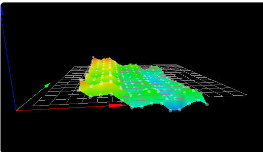
Hi All. here is the latest height map data:
G29
210 points probed, min error -0.175, max error 0.220, mean -0.003, deviation 0.092
Height map:

Result from G32:
G32
Manual corrections required: 0.00 turn up (0.00mm) 0.01 turn up (-0.01mm) 0.12 turn up (-0.06mm) 0.07 turn down (0.03mm)
Print:

Must admit this is the best print using mesh bed compensation I've got so far but no where near as good as the print achieved without it ??
If you study the height map in relation to the print you can see the lower points on the height map are in deed where the nozzle is touching the bed. Which suggests mesh bed compensation is working. But the bed is not as low as G29 thinks it is, at those points.
Again I ask why does a Z of a G32 probe point on the bed NOT equal a Z of a G29 probe of the same point ??
-
that suggest that there is a tilt in the hotend.
this causes the z offset to be higher on the left and lower on the right.
the probing however needs this offset to be constant.this could be due to problems with the wheels on the x gantry
or the wires pulling on the hotend assembly, twisting the entire assembly. -
Cheers I will look into that.
-
Ok I have now check mechanical and have to say I don't find any issues.
Next I will be mounting a DTI on the head and see if I can make progress or improve my understanding.
Can I ask, am I trying to probe the bed at the points where the nozzle would be? or does the firmware calculate for the offset ?In my case should I be probing at X45 Y-55, and would this relate to nozzle X0 Y0 ?
Or have I been at this too long and brain freezing?????