Another Stratasys uPrint retrofit
-
I'm now working on a stratasys dimension 1200sst, but it was working when I got it vs dealing with a gutted uprint.
The stock hotend runs on 120VDC. I just read the service manual, it documents all the test points and you can just plug into those to get the sensor data you need.Do you have a cad model of the photo above?
This is one I found on grabcad and have modified.
https://a360.co/2UyWBvrHere's the printhead I'm modifying to fit a nema 17 stepper and a bondtech BMG.
https://a360.co/2yiIT7lHere's an adapter plate to mount the duet in the 1200SST with GEN2 Electronics
https://a360.co/2X0NHIN -
@AJ-Quick That is Freekin amazing!!! do you have the pinout of those headers you can share with me? I'm in the middle of retrofitting my 1200SST.
-
@AJ-Quick Here is my Github repo for the uPrint & 1200SST
https://github.com/drphil3d/stratasys -
I have now spent a solid 12 hours writing out and compiling notes for the uPrint. I think you will find that the main PDB connections are probably the exact same between the uPrint and 1200SST. That means in all likelihood, if my board works for the uPrint, it will probably work for your 1200SST too. Consider leaving everything intact with your setup if you can wait a month or two for me to get things further along.
Here is what I've written out so far: https://wiki.cnc.xyz/Stratasys_uPrint_Retrofit
You will likely want to look into the J13-J15 pins (on the uPrint, they may be called something else on the 1200's board):
https://wiki.cnc.xyz/Stratasys_uPrint_Retrofit#Power_Distribution_Board_.28PDB.29
I've written out what I believe to be accurate regarding the pin out. I had a few problems reading my notes however.
I think Pin 6 on J14 (Print Head Type B) and Pin 31 on J15 (Print Head Type A) are probably the only differences between the Elite line and the uPrint line. I'm guessing the uPrint has the "toggle" head and the 768 and 1200 have something different?
Looking at a photo of the Dimension PDB. Looks like they have the connectors listed as the following (I've also written what they are on the uPrint).
J17 = J15 on uPrint
J19 = J14 on uPrint
J14 = J13 on uPrintWhat you can do to help me:
-
If possible, trace any pins on your power distribution board. If you can find out where the pins go. For example on J13 (J14 on your Dimension) you have all the motor control signals. If you can verify what signals are the same, that will be helpful.
-
Find out what driver chips are present for the stepper motors. On the uPrint they are Allegro A3959 SMD's. On the 1200, they are a different type on those big heatsinks.
-
Likewise, next to the three driver chips, there is a DC servo motor driver. On the uPrint it is a STMicroelectronics L298P. I'm guessing it is the exact same, but if not, let me know.
-
What test points are available, I couldn't see them all on the photo you have on the Github.
On your uPrint: Did you run into any problems with the Stratasys provided +5/12V power supply? I found that the minimum required load for the factory power supply was just too high and then Duet did not draw enough power from it. I had to replace it with a different power supply, I'll have to find the model I used as you may need to also replace yours.
From Github:
-Cons Display firmware doesn't support rotation of 90degrees Expensive
Yes! I've been asking for a long time to see if we can get an option to rotate the display on the PanelDue for the exact reason that it would look better vertical on the uPrint. Maybe if a few of us are requesting it, it can be added? I could not figure out how to do it myself.
See here: https://github.com/dc42/PanelDueFirmware/issues/24
(I did not try what I had suggested there as I was not compiling my own firmware at the time.)
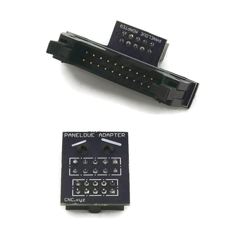
Also. I created plug and play adapters for the PanelDue. The LCD plugs directly into the Stratasys wiring on the uPrint (may be same for Dimension). The ribbon cable coming off of the Stratasys board plugs into the Duet. Check if the ribbon cable on your PDB (looks like J15) is for the front panel. If so, that should work on yours as well.
-
-
@AJ-Quick Awesome work! If only I had space for one of these...
Ian
-
Yeah, it looks quite similar to mine, although the print head board is different.
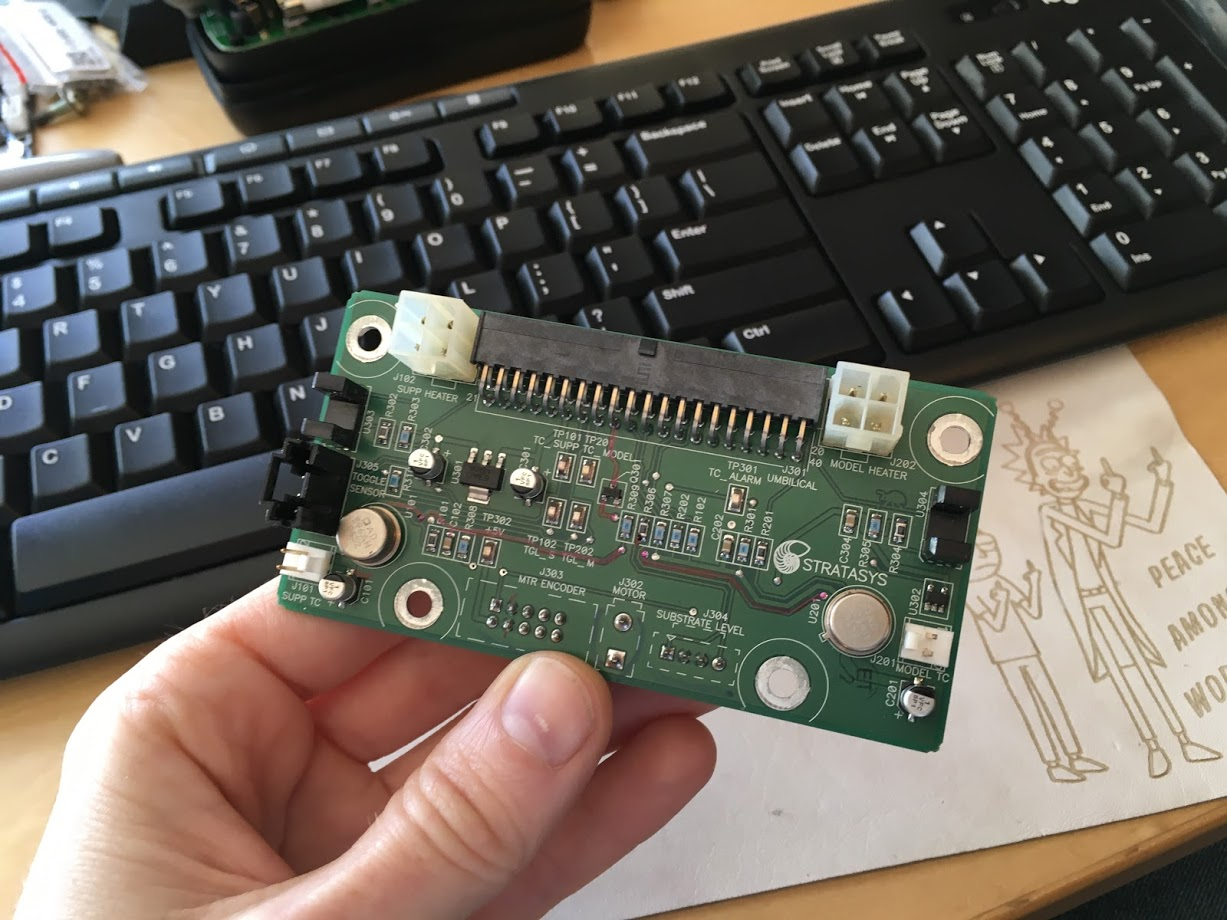
I haven't really cut anything yet, I was going to leave the optical end stops intact and what ever other sensors that I could leave for later use.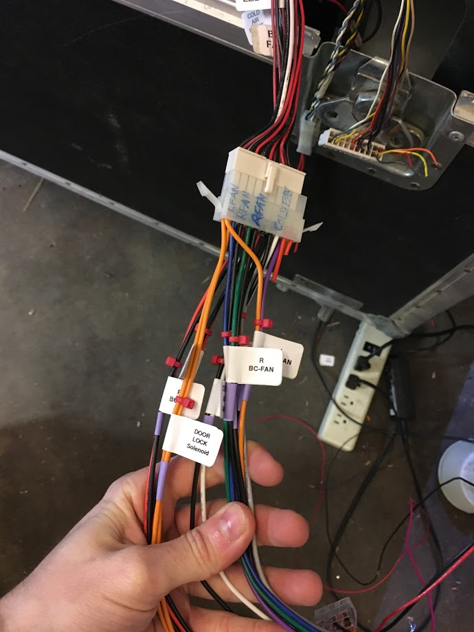
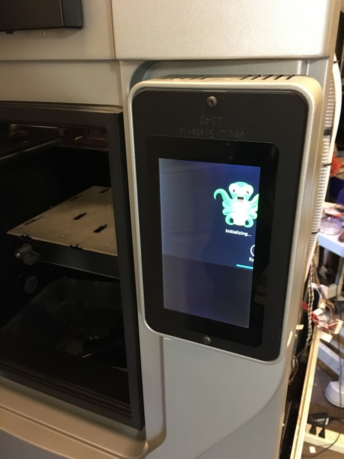
As for the stepper motors I decided it would be far easier to use the Duet TMC drivers and take advantage of the sensorless homing so that I don't have to worry about wiring any of the endstops. It works quite well, and I have the advantage of being able to use the stall guard feature for crash detection during printing.I got rid of the lcd and replaced it with a raspberry pi touchscreen. Unfortunately Octoscreen (octoprint UI) won't run when rotated 90*. The Panel Due does not support 90* rotation either.
 Frustrating.
The stock hotend design is only going to work for printing pc-abs or other high tempature materials that won't deform at lower temperatures. Due to this limitation I'm replacing the extruder assembly with a single hotend for now. I may have a custom 120 watt 24v heater core made for this, the owner of this company is a friend of mine so it makes this easier for me to acquire.
https://ubishotends.com/shop/xx9ppgi6moubdjx5kscfk8md4e8ecb -
It looks to me like the chamber heaters are driven by a mosfet, that first must be enabled by a relay, I',m not completely certain. My goal is to try and tap into the signal inputs for mosfet and relay and wire that to the heated bed output on the duet, that way I wouldn't have to cut any wires.
I see pin 16 of J15 is power enable, I'm assuming that it wants +5v for power enable?
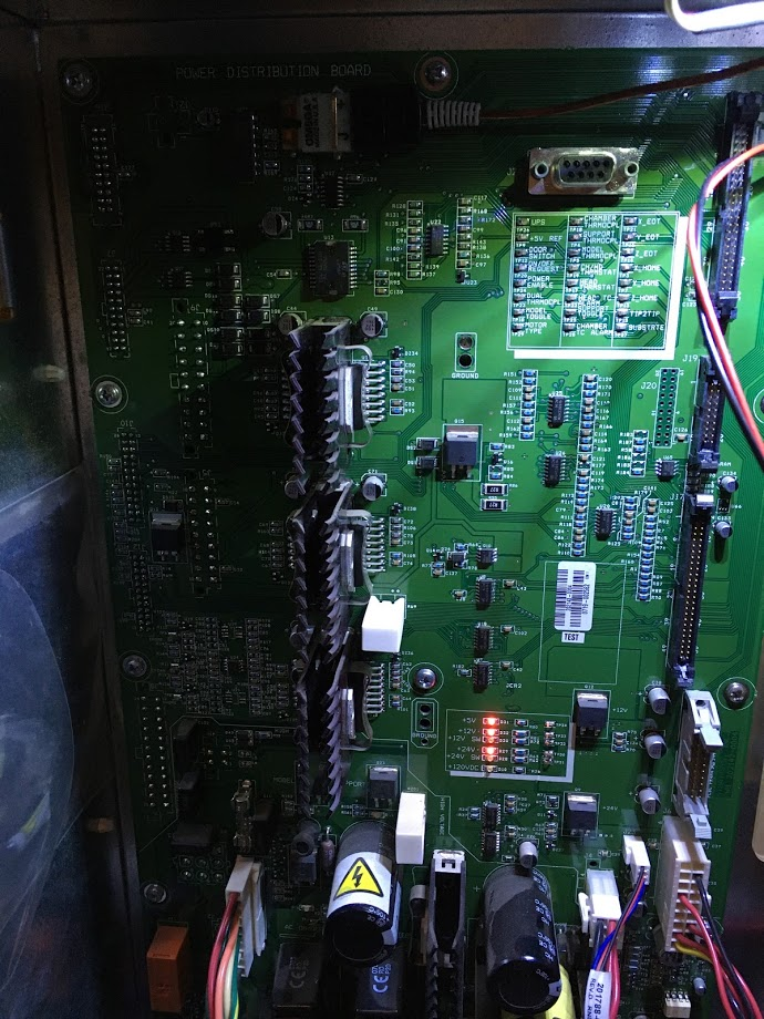
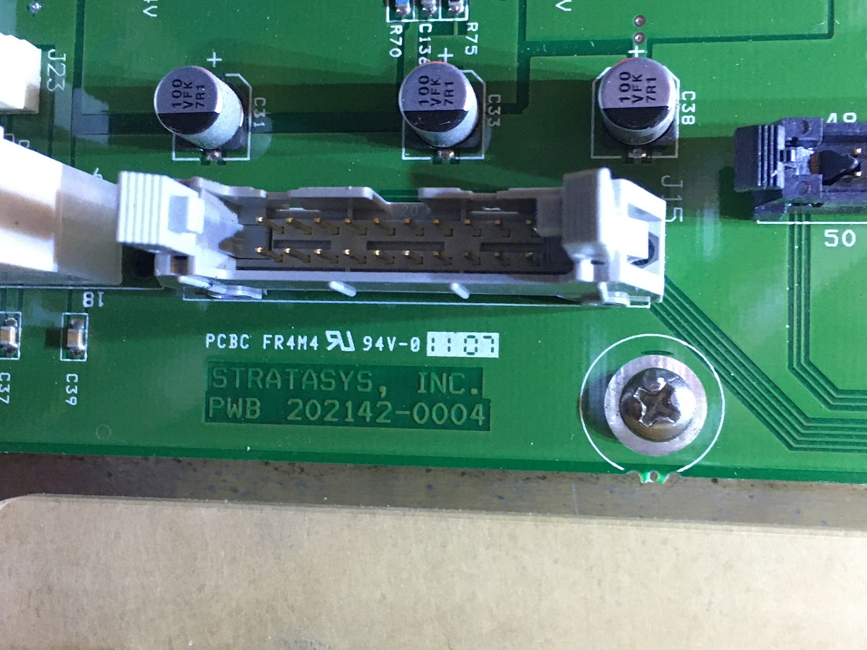
-
My PDB is different than yours, It looks like the ports have different labels. I was able to connect the +5V Reference Test point to Power Enable to power the board on. But that's also powering the Stepper drivers and other things I don't necessarily want turned on. I still need to figure out how to apply power to the Chamber heaters, looks as though the relay to the left of the SSR needs to be enabled first.
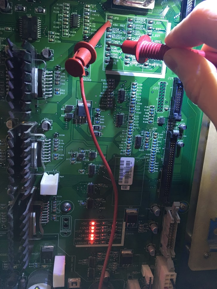
Stepper Drivers
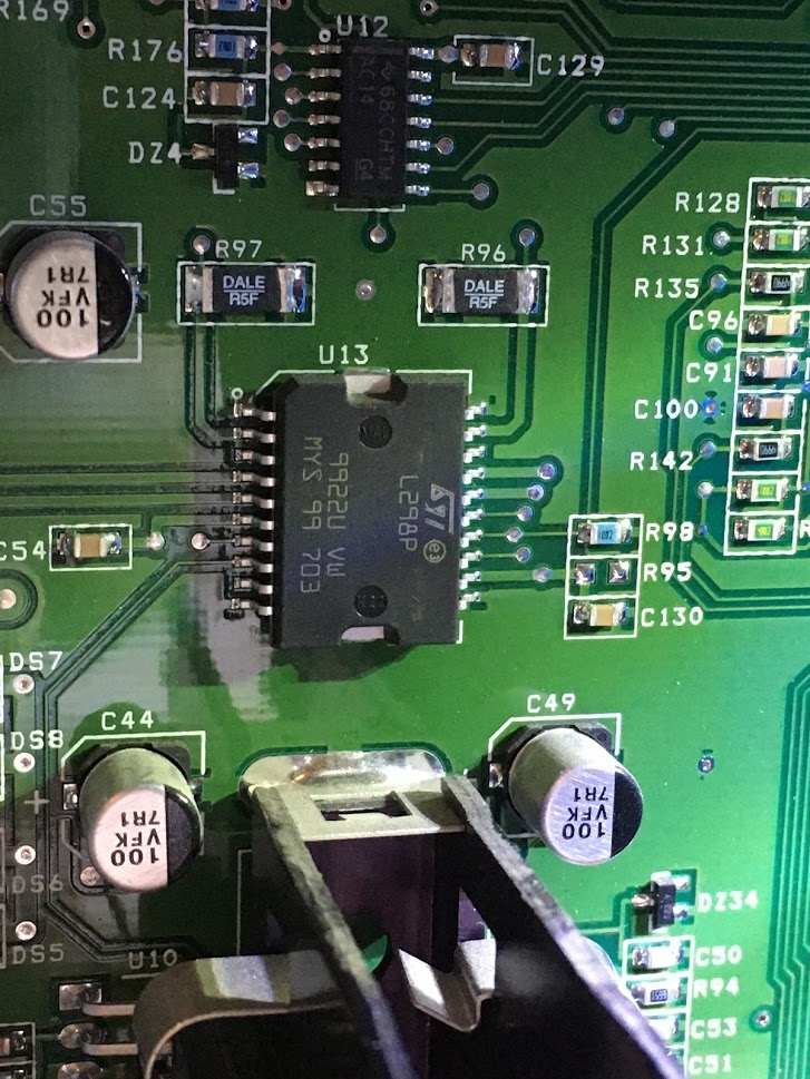
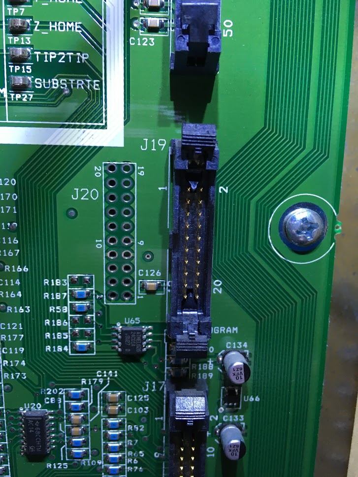
-
@drphil3d said in Another Stratasys uPrint retrofit:
I got rid of the lcd and replaced it with a raspberry pi touchscreen. Unfortunately Octoscreen (octoprint UI) won't run when rotated 90 *. The Panel Due does not support 90 * rotation either. Frustrating.
Perhaps have a look at the DueUi project: https://forum.duet3d.com/topic/13970/dueui-release-3-0-1-beta2-available
-
@drphil3d said in Another Stratasys uPrint retrofit:
Yeah, it looks quite similar to mine, although the print head board is different.

Oh that's interesting. It seems they have combined both the head thermocouple board and the head functions board (power / servo motor / extruder heat.. etc) onto one PCB. On the uPrint they are separate boards.
@drphil3d said in Another Stratasys uPrint retrofit:
As for the stepper motors I decided it would be far easier to use the Duet TMC drivers and take advantage of the sensorless homing so that I don't have to worry about wiring any of the endstops. It works quite well, and I have the advantage of being able to use the stall guard feature for crash detection during printing.
To be honest. That is really easy to do. You can hook the Duet stepper wires up directly to wires coming into the system. I'm not sure if the X, Y and Z motors are on their own connectors like they are on the uPrint. If they are, you can get Molex connectors to plug directly into them. My first test with the uPrint was to make wiring harnesses that connect the motors to the Duet.
That being said. I would still highly recommend keeping all the limit switches in place if at all possible. It should be possible to do both the Duet's drivers and the Stratasys limit switches.
@drphil3d said in Another Stratasys uPrint retrofit:
The stock hotend design is only going to work for printing pc-abs or other high tempature materials that won't deform at lower temperatures. Due to this limitation I'm replacing the extruder assembly with a single hotend for now.
I didn't consider this. Is the stock extruder not able to print PLA and other lower temp materials?
@drphil3d said in Another Stratasys uPrint retrofit:
My PDB is different than yours, It looks like the ports have different labels. I was able to connect the +5V Reference Test point to Power Enable to power the board on. But that's also powering the Stepper drivers and other things I don't necessarily want turned on. I still need to figure out how to apply power to the Chamber heaters, looks as though the relay to the left of the SSR needs to be enabled first.
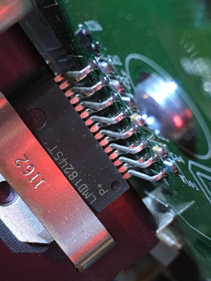
I don't think there is anything you can do to get around the Stepper Motor drivers from being enabled, other than also enabling the 'all motor drivers sleep' command. If you can't find it, it may be Pin #10 (BRAKE) on the LMD18245 stepper motor driver. Setting that pin logic high (apparently up to 12V) on that chip, may put the drivers to 'sleep'.
The MOSFETS to turn the heaters on/off, LED lights (if equipped), door lock solenoid are located between the stepper motor drivers and the power connections.
From your pictures:
Look at the traces from the touch points and follow them, most of them go to J17. Compare to J15 on the uPrint. You will find most of the touch points are broken out on that connector. This is where you will be able to control the chamber heaters, read the thermocouples, read the limit switches.. etc. Of course you could just as easily solder wires on to the touch points and have them broken out that way too.

If you have a continuity tester:
Connect one end to the touch point and then find continuity back at J17. (Make sure the power is off for this, so you don't short out the connection in J17). For example, the touch point for chamber heat is there, find where it gets broken out on J17. Alternatively, you 'may' be able to jumper power from the +5V ref to the chamber heat touch point to get it to turn on. You may also need to activate the power enabled touch point at the same time.
@Phaedrux said in Another Stratasys uPrint retrofit:
Perhaps have a look at the DueUi project: https://forum.duet3d.com/topic/13970/dueui-release-3-0-1-beta2-available
This is interesting. In my case, I would want to keep everything running on one board with the PanelDue though. That's why I prefer Duet2 vs Duet3.
-
@AJ-Quick said in Another Stratasys uPrint retrofit:
That's why I prefer Duet2 vs Duet3.
Duet3 can run as a standalone board as well btw.
-
I traced the pins and found that J15 is the same as J17 on the 1200SST, I was able to enable the heated chamber and other accessories. Now I face another issue, how do I control it. I can't use the heated bed output on the duet sense that would feed 24v into a 5v pin...aaaahhh.
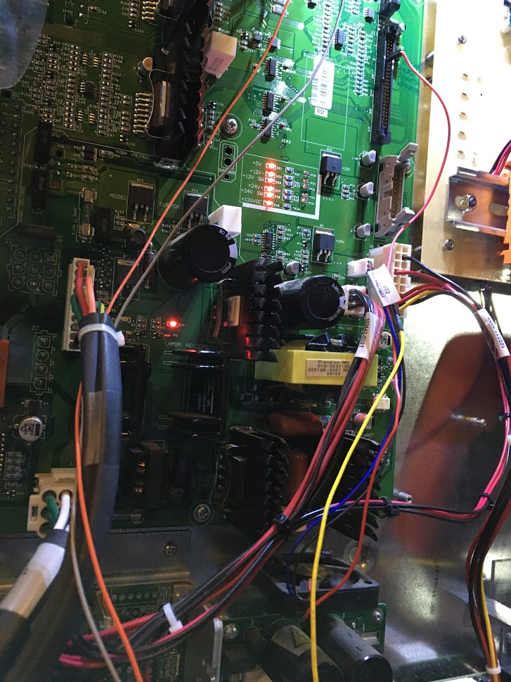
This thing is such a beast
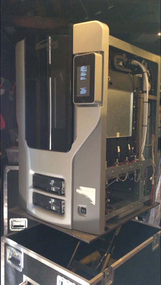
-
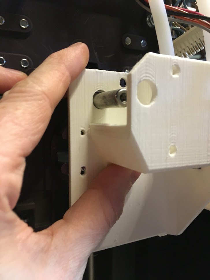
This is my first attempt at a mounting solution for a bondtech bmg extruder. The pin in the middle really gets in the way.
The stock hotend has a number of drawbacks that limit its usefulness.- Not going to print PLA, or anything even the slightest bit flexible the way it's designed. That PC-ABS 430 has a very high glass transition tempature. The oem hotend (liquifier) isn't really meant for printing any low tempature materials.
- non metric nozzle size is going to make slicing interesting
- No or very little retraction. They call it a liquifier for a reason, pc-abs has some unique properties designed for this printhead.
-
@drphil3d said in Another Stratasys uPrint retrofit:
I traced the pins and found that J15 is the same as J17 on the 1200SST.
Great to hear! That's exactly what I was guessing since they both use the same controller board and on-board computer.
@drphil3d said in Another Stratasys uPrint retrofit:
I was able to enable the heated chamber and other accessories. Now I face another issue, how do I control it. I can't use the heated bed output on the duet sense that would feed 24v into a 5v pin...aaaahhh.
The easiest thing you could probably do is connect to a controlled fan output at 5V (this is possible right?). Or get a I/O 3.3v to 5.0v logic level shifter such as the TXS0108E and then connect to the EXT pins.
-
Yeah, that's exactly what I was thinking. Change the jumper to 5V on one of the fan outputs and connect that to the heated chamber, then figure out how to update the config to use the fan pin for chamber heater control.
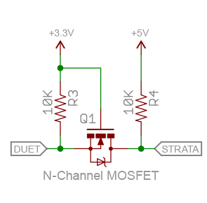
Another option I was just thinking of, is I could breadboard a transistor and some resistors to signal the chamber heater using one of the 3.3v pins on the duet.
I would drive the heated chamber mosfet directly, however they used a mosfet that has a control voltage limit of 15v, otherwise I could just feed the heated bed output directly to the heated chamber test point pin (TP2).
-
@drphil3d said in Another Stratasys uPrint retrofit:
Another option I was just thinking of, is I could breadboard a transistor and some resistors to signal the chamber heater using one of the 3.3v pins on the duet.
Sure. That's basically one one direction logic level shifter. Here is an example:
-
@AJ-Quick sorry I have been away for a bit and received no notifications.
A bit pressed for time but I will come back and follow up in the next day or two. Short version; and I may be repeating myself but I haven't gone back to re-read.
Integration progresses slowly. I ended up driving the motion steppers directly from the Duet. On the uPrint, each stepper has a discrete connector into the electronics enclosure. So I just ran an umbillical direct to those connectors and bypassed the uPrint electronics entirely.
I used logic level shifters to fire the chamber heater and system power SSR's. Same for the extruder heaters. Same for endstop signals going back to the duet.
I tried a simple resistor voltage divider network for the thermocouple signals but that wasn't successful due to protective resistors on the uprint electronics. Then I realised at the 10 mV/ C signal level, any designed temperature was going to be within the duet ADC allowable levels so I scrapped the voltage divider and now have reliable cabinet temperature sensing. Extruder is being strange and I haven't quite figured out the slope / offset going on there or how I'm supposed to get that calibration in the linear analog mode of reprapfirmware.
I am now protecting the ADC inputs with a 3V3 zener across each input.
Started on the PicServo integration and ran into headaches trying to interface to the H-Bridge in the uprint. I am now waiting for parts to build a patch lead that will go between the applicable chassis loom / electronics enclosure that will let me pull out the servo power and encoder wiring direct to the picservo board. This way the modification is still entirely non invasive.
I actually had a call from the printer owner asking about lead time to return the printer to factory as they were being asked about printing face shields. Pity the build volume isn't big enough to actually run that print.
While I wait for parts I have gone back to a separate job of integrating a duet to an old Prusa clone. Had some issues where the duet smoked a borrowed PanelDUE and also failed it's WiFi module

-
@AJ-Quick said in Another Stratasys uPrint retrofit:
Pete,
Have you continued to make progress?
Yes

Would you be able to share what you have done to make the integration a success so far? For example how connections have been made between the Duet and the Stratasys boards? Have you managed to integrate the material bay in anyway?
Biggest problem I hit when trying to be drop-in replacement was the driving the steppers. The TMC drivers appear to be adequate to drive the stepper motors but they are too smart for their own good. If you try to drive the uPrint power amplifiers with the TMC drivers, the TMC's get confused since there isn't a real stepper on the output providing back EMF and all the other goodies that let the TMC driver do it's job. If you use the Duex outputs of step/direction then you are limited to whole steps I believe and then we waste the potential of such a rigid motion gantry. I ended up just running an umbilical out through the grommet on the LHS of the electronics cabinet. With each motor having its' own connector into the cabinet, this was simple and still non invasive.
For now I'm not touching the material bays. I'd like to come back to that problem at a later date since the load/unload mechanism is really nice.
I have been working on something very similar. The goal was to make it completely plug and play. Ethernet Duet in, while still completely maintaining the Stratasys motor controllers, thermocouplers, servo drive and dual extruders. Something that can be dropped into any uPrint and be operational in only 30 minutes or so.
Some questions I have:
How did you change from the Duet's Step / Direction signals into the PWM signal the Stratasys board requires? Did you bypass the Stratasys board to run the steppers from the Duet directly?
My understanding of the stepper power amplifier block is that it functions basically like one side of an H-Bridge but it provides current limiting for each winding. It still takes step/direction inputs. I have a link someplace where the question was asked and explained. It is an unusual implementation of the driver chip, but it does work. As mentioned above, it doesn't work with the TMC drivers on the Duet so I bypassed the whole lot.
The extruder is a DC servo motor, hence the PicServo. I haven't gotten very far with that because (again), I got wrapped around the axles trying to use the existing power amplifier hardware. I will be bypassing that also. Just waiting on the required connectors to test the prototype idea.
I am keeping all of the mechanical hardware completely original; Stratasys did a fantastic job and I don't want the headaches of trying to make a reliable hotend assy when the hardware in there is excellent.
If you want to share / work together I'd love to help get something off the ground here. I have lots of information, pinouts.. etc written down somewhere. If I ever got it working, I'd be doing open source and conversion kits. Now that I know more people are trying to achieve the same, I'd be happy to start compiling data and code to post on Github.
My intention has always been to make the BOM, wiring data and gerbers available. I have no desire to supply hardware kits; been there, done that, not interested. I have started pushing bits and pieces up to github but I'm still getting my head around that ( I'm a system integrator, not a software guy).
For expectation management, I'm doing this in slow time for my own enjoyment. I will eventually have something usable to release but I'm not setting any sort of deadline. Happy to collaborate if you are interested, flick me a PM and we'll take it offline.
-
@Pete_A said in Another Stratasys uPrint retrofit

My understanding of the stepper power amplifier block is that it functions basically like one side of an H-Bridge but it provides current limiting for each winding. It still takes step/direction inputs. I have a link someplace where the question was asked and explained. It is an unusual implementation of the driver chip, but it does work. As mentioned above, it doesn't work with the TMC drivers on the Duet so I bypassed the whole lot.
Yes! I was totally used to using drivers that controlled both sides of the H-Bridge simultaneously. To come across this weird DC motor controller being split into two phases really threw me through a loop. You are correct that you can essentially hook up a Step / Dir signal, but to be super effective it should be a PWM signal that can micorstep.
That person that asked the question was me! https://electronics.stackexchange.com/questions/398928/interfacing-with-two-full-bridge-pwm-motor-drivers-to-control-a-stepper-motor
Check out the page I started writing about the uPrint here: https://wiki.cnc.xyz/Stratasys_uPrint_Retrofit
It outlines how to operate the on-board steppers, servo and reading things like thermocouples. Unfortunately right now it's all just theoretical. I'm waiting for my new PCB adapter boards to arrive next week. I'm feeling pretty good about it though. In theory I will have every function controlled by the Duet (except for the Material Bay) by the end of next week.
-
I'm trying to post a useful reply but the stupid akismet spam filter keeps blocking me for some reason

Small world :). The provided explanation was really helpful. When I first saw the circuit diagram and design constraints I just knew it was for a uPrint.
Pins arrived today for my extruder splice loom. No connectors though

Had a quick look through the wiki page; nice and concise. Would have saved me a bunch of work
