Another Stratasys uPrint retrofit
-
Pete,
Have you continued to make progress?
Would you be able to share what you have done to make the integration a success so far? For example how connections have been made between the Duet and the Stratasys boards? Have you managed to integrate the material bay in anyway?
I have been working on something very similar. The goal was to make it completely plug and play. Ethernet Duet in, while still completely maintaining the Stratasys motor controllers, thermocouplers, servo drive and dual extruders. Something that can be dropped into any uPrint and be operational in only 30 minutes or so.
Some questions I have:
How did you change from the Duet's Step / Direction signals into the PWM signal the Stratasys board requires? Did you bypass the Stratasys board to run the steppers from the Duet directly?
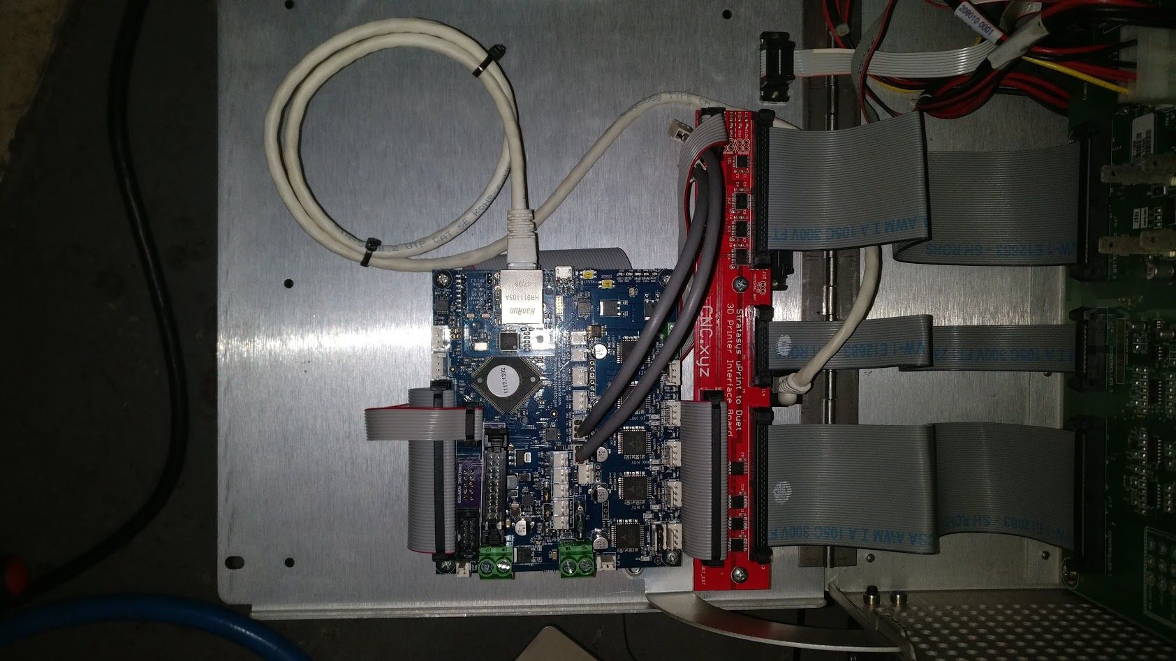
Similarly, how did you handle the servo motor and encoder for the extruder? Did you use a third party DC servo controller (such as Geckodrive G320X) and bypass the Stratasys electronics?Scratch that. I see you are using PICServo to adapt the signal. That's actually a similar direction I was going, but using an ATtiny85 with somewhat standard step / dir to PWM with encoder feedback. I got the extruder servo spinning, but need to flash new code to the Attiny85, which requires a high voltage programmer I don't yet have.Here is a photo of the setup I was working on:

Chips from left to right:
(1) ADC MCP3208 that converts the data from uPrint Thermocouples into SPI data that the duet could read through the CurrentLoopTemperature code. (See code here) Check this if you are having problems getting the right TC data from the uPrint.
(2) (3) (4) Chips that convert signals from 5V to 3.3V in a bidirectional manner.
(5) Attiny85 that converts Step / Dir data to PWM with encoder feedback for servo extruder
(6) (7) (8) Attiny85 for the X, Y, Z. Takes Step / Dir data and converts to PWM for half bridge chips / microstepping.The limit switches needed to be hardwired directly to the X, Y, Z, E0, E1 but if I recall they were not explicitly for those axis and were instead for things like light control, door open switch, locking solenoid. (I did get the Duet to control all of those things).
You are absolutely right that these uPrints are literally gathering dust and have outlasted their useful life for many of their end users. I paid $25,000 for my first uPrint brand new. However they are now popping up on eBay from time to time for next to nothing. I have bought several of them for around $300 each! The main thing holding them back was always the $200 per spool proprietary filament that greatly lagged behind the quality and innovations that were occurring in the hobby field, as well as the software that forced the best print quality to be 254 microns when DIY printers were easily achieving 50-100 micron.
The hardware on the uPrint is phenomenal. It is capable of so much more than Stratasys will allow through their software.
If you want to share / work together I'd love to help get something off the ground here. I have lots of information, pinouts.. etc written down somewhere. If I ever got it working, I'd be doing open source and conversion kits. Now that I know more people are trying to achieve the same, I'd be happy to start compiling data and code to post on Github.
-
Hi Aj Quick,
It is really cool to see what you did!
I can´t even begin to understand how you did the probing of the control board to figure out what signal goes where?
I assume you´re an electrical engineer of sorts?
I am working on a "similar" project, pretty much exactly the opposite of what @drphil3d did.
I got myself a used uprint print head (say that 5x quickly) and want to install it into my own heated build chamber printer. I am currently reverse engineering it. I also have two extra sets of new nozzles and about 27 spools of model material and 5 spools of support material.
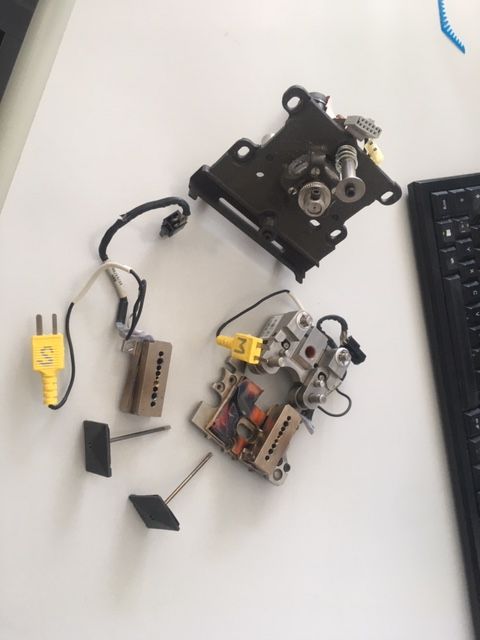
The print head is capable of so much more than ABS. They are the same stainless steel construction as in the Fortus machines and can easily do 420+°C for my high temp polymers.
I couldn´t help but overlook that you said DIY printers can easily achieve 50 micron while the Uprint is "stuck" at 254 micron.
This isn´t quite true.
I think you missed what the strength of the Stratasys machines is.
The point isn´t to make the most detailed, flawless Yoda heads in PLA. You can do that on SLA machines if you wish.
The point is to make dimensionally accurate (!), complicated and even moving mechanisms with total geometric freedom due to the soluble support material, printed FAST. This is the important part for engineers, and why stratasys continues to thrive today even with all the low cost competitors.There is simply no other hassle-free, tinker-free, one-click dual extrusion system that can do the same as stratasys and it´s all because of their ingenious print heads!
- They raise their second nozzle so as to not marr the print with oozed material.
- they have a tip shield in order to prevent smearing the plastic on the heat block when they wipe the nozzle.
- The heat blocks and liquefier tubes are stainless steel in order to prevent contact corrosion due to the galvanic (electropotential) series. SS is not the best heat conductor but is necessary at these high temperatures to prevent corrosion.
e3d still does not realize that and continues to market copper blocks as "the shit". I´ve used them for printing PPSU (400°C) and at some point the nozzles are just stuck in the block, they have just corroded in. Just the same as their PT100 sensors, they are stuck in the block and you have to throw the whole block away.
Also,the nozzle geometry is unsuitable for dual extrusion as it promotes oozing.Anyway, the upper three points are why i want to try the uPrint head in my own printer.
What i am still missing is how to drive the 120VDC servo.
How did you realize that ? -
@NitroFreak said in Another Stratasys uPrint retrofit:
I can´t even begin to understand how you did the probing of the control board to figure out what signal goes where?
I assume you´re an electrical engineer of sorts?I'm a mechanical engineer, but do complete integrations of electronics and software as well. As far as the probing is concerned, it didn't actually take too long. My process was mostly this:
Find where a known connection enters the board such as a motor. Find the continuity between the motor pins and the motor driver chip. Look up the motor driver chip's datasheet to determine what pins do what. Follow the traces back from there to the next point of interconnection. Eventually you find that Pins 1, 3, 17 & 19 on connector J13 are what you need to interface with to control the X-axis stepper motor by sending Phase PWM and voltage reference signals for example.
If you send the right signals there (following the motor driver datasheet) you'll get controlled movement out of the stepper motor using all of the Stratasys' built in electronics.
@NitroFreak said in Another Stratasys uPrint retrofit:
I couldn´t help but overlook that you said DIY printers can easily achieve 50 micron while the Uprint is "stuck" at 254 micron.
This isn´t quite true.
I think you missed what the strength of the Stratasys machines is.I actually greatly understand the rock solid nature of the hardware on the machine. That's why I want to push it to it's full potential by opening up the ability to print PLA, Nylon.. etc at whatever layer thickness I want. The idea that it is dimensionally flawless is a little misguided. I had TONS of failed prints on the uPrint. I had numerous times where the part failed spectacularly in a mess of spaghetti or when the filament spooled up in the head and fused the print head into a solid block of ABS. When you're spending $50 per print, you can't have that happening.
The quality of the proprietary ABS was poorer than the stuff you could buy for $15 per spool. I had Stratasys' technicians out to troubleshoot my brand new machine and we went through every single spool of filament I had and determined each one was filled with too much moisture and had to request Stratasys replace them all. Eventually it made more sense to buy a genuine $200 roll of filament to get a new eprom and a $15 roll of a no-name brand ABS, spool it onto an empty reel and use it instead of the expensive stuff.
You can have just as great dimensional accuracy on a cheap printer. It just may not print as fast and may require more adjustment. I think you may be disappointed in the amount of effort it takes to put the Stratasys extruder on your build when compared to what other options are out there.
You may not have an easy time finding replacement parts should something break either. You'll be stuck buying used parts.
@NitroFreak said in Another Stratasys uPrint retrofit:
Anyway, the upper three points are why i want to try the uPrint head in my own printer.
What i am still missing is how to drive the 120VDC servo.
How did you realize that ?It's fairly straight forward. Look up the model number on the servo drive. You'll find it is a proprietary part number, but the company that makes them has other similar models to look up the datasheet. You should see that the IDC 10 pin connector from the servo is a common pinout. You've got motor power and the 2 or 3 encoder signals (2 differential signals, plus ground I think).
You can hook that up directly to a servo driver, such as the Geckodrive G320X. Note: The servo does not run on 120VDC, probably something like 12V or 24V, but I don't remember off the top of my head.
The heaters run on 120VDC. You'll need a very high quality DC:DC relay to turn those on and off. Don't skimp out on that, it's some serious voltage. If you can snag two 120VDC power supplies from a Stratasys machine that would help. Note that each printer has two power supplies at 120VDC, but one is a modular supply and one is built into the main Power Distribution Board, so you'd need parts from 2 different printers.
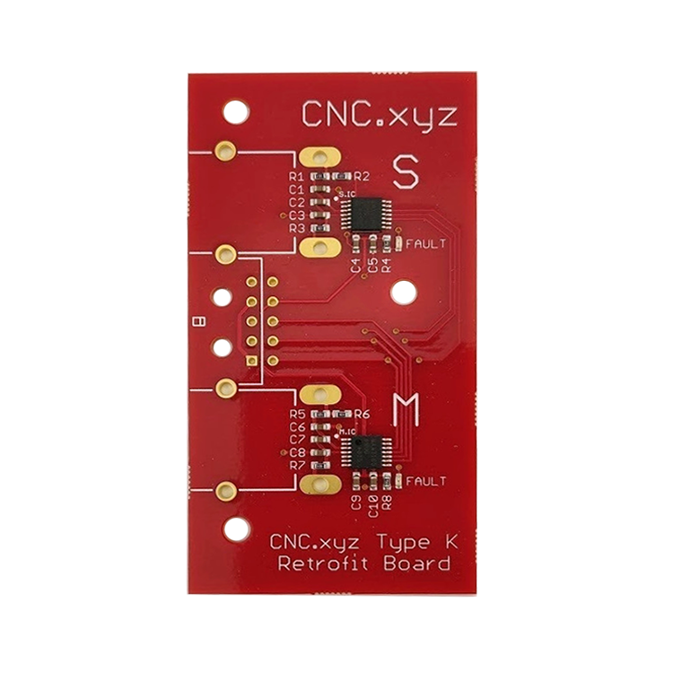
If you are interested I designed and made a prototype head thermocouple board that takes the temperature readings from the Stratasys thermocouples and converts the signal directly to SPI. It mounts directly to the Stratasys print head. (The standard board uses voltage reference to produce the signal that must be interpreted later.)
-
@AJ-Quick
Thanks for the detailed explanation! Now that you explained it, it doesn´t entirely sound like witchcraft anymore.I´m not entirely sure if i´m going to use the print head as is, but i definitely want to use the tips (nozzles) and heat block style. But i´m probably going to machine the heat block myself to have a different mounting interface. I have access to a big machine shop so i can make pretty much anything.
I forgot to mention in my other post that you can use MaracaEX to print at any layer height you wish. HaveBlue did a post on that IIRC, however i can´t find it now.
I´m not entirely sure if this also applies to the newer uPrint models, but i have a Dimension 768 BST and i can use an old version of Insight to slice models for that. It also gives loads of options.It´s a shame that you had moist material, my spools have a lot of moisture too, but when you dry it beforehand it´s the most beautiful material you´ll ever print, especially if you have access to a 90C heated chamber. It´s SABIC MG94 High flow resin, and it is quite exquisite. I usually just put the spools in the bottom of the chamber while it´s printing, it comes out to about the perfect temperature for drying.
Since the heater cartridges are oblivious to if they´re being run with AC or DC, i planned to just wire them in series and run them off of a 230v SSR. Is there a flaw in that thinking?
For the Thermocouple, i bought a Duet Thermocouple daughterboard. Do you know what kind of Thermocouple it is? I planned on holding them in boiling water and just trying the different configurations until one fits and shows 100C.
The Geckodrive is quite expensive, i may sell the servo and just put in a normal geared nema 17 maybe.
Where are you based? If i can find a used uPrint for a reasonable price I´d definitely be interested in a set of electronics from you.
-
Ahh. If you're not using the same linear setup from the Stratasys, it may not be of benefit to you. You would need the X-axis to mount the board to. Here is a photo for reference, it replaces the stock thermocouple board and uses two MAX chips. I ended up going a different direction to keep the Stratasys boards in tact.
@NitroFreak said in Another Stratasys uPrint retrofit:
For the Thermocouple, i bought a Duet Thermocouple daughterboard. Do you know what kind of Thermocouple it is? I planned on holding them in boiling water and just trying the different configurations until one fits and shows 100C.
The Thermocouples are type K. You should actually be able to connect them directly to the Duet thermocouple daughter board, just be aware that they will not be compensated for the chamber heat in the same exact way they will be on the Stratasys electronics since the daughter board should be outside of your (hopefully) heated chamber. That and if you are extending the leads, you may also introduce more problems. If you can find a suitable replacement Type K thermocouple with long leads, I'd do that instead.
@NitroFreak said in Another Stratasys uPrint retrofit:
I forgot to mention in my other post that you can use MaracaEX to print at any layer height you wish. HaveBlue did a post on that IIRC, however i can´t find it now.
I´m not entirely sure if this also applies to the newer uPrint models, but i have a Dimension 768 BST and i can use an old version of Insight to slice models for that. It also gives loads of options.Unfortunately the uPrint is very locked down through software. The Dimension was more accessible to modifications, but typically used a worse extruder setup. The uPrint uses a different slicer utility that locks the layer height, but you can still use MacaraEX to make firmware adjustments to temperatures.
@NitroFreak said in Another Stratasys uPrint retrofit:
It´s a shame that you had moist material, my spools have a lot of moisture too, but when you dry it beforehand it´s the most beautiful material you´ll ever print, especially if you have access to a 90C heated chamber. It´s SABIC MG94 High flow resin, and it is quite exquisite. I usually just put the spools in the bottom of the chamber while it´s printing, it comes out to about the perfect temperature for drying.
My long term solution was to dehydrate the spools for several hours in a large food dehydrator and store the spools in insulated food coolers with desiccant bags. It certainly did help. The uPrint can only use the ABS-400 material and soluble support material though. No other materials are allowed even though it certainly could handle them.
Since the heater cartridges are oblivious to if they´re being run with AC or DC, i planned to just wire them in series and run them off of a 230v SSR. Is there a flaw in that thinking?
That certainly is a possibility. You could buy replacement heater cartridges, especially if you want to design your own heater block too.
The Geckodrive is quite expensive, i may sell the servo and just put in a normal geared nema 17 maybe.
That might not be a bad idea, though the servo is reasonably small and powerful for it's size. You may run into a speed bottleneck.
Where are you based? If i can find a used uPrint for a reasonable price I´d definitely be interested in a set of electronics from you.
I'm in Colorado, US.
-
I'm now working on a stratasys dimension 1200sst, but it was working when I got it vs dealing with a gutted uprint.
The stock hotend runs on 120VDC. I just read the service manual, it documents all the test points and you can just plug into those to get the sensor data you need.Do you have a cad model of the photo above?
This is one I found on grabcad and have modified.
https://a360.co/2UyWBvrHere's the printhead I'm modifying to fit a nema 17 stepper and a bondtech BMG.
https://a360.co/2yiIT7lHere's an adapter plate to mount the duet in the 1200SST with GEN2 Electronics
https://a360.co/2X0NHIN -
@AJ-Quick That is Freekin amazing!!! do you have the pinout of those headers you can share with me? I'm in the middle of retrofitting my 1200SST.
-
@AJ-Quick Here is my Github repo for the uPrint & 1200SST
https://github.com/drphil3d/stratasys -
I have now spent a solid 12 hours writing out and compiling notes for the uPrint. I think you will find that the main PDB connections are probably the exact same between the uPrint and 1200SST. That means in all likelihood, if my board works for the uPrint, it will probably work for your 1200SST too. Consider leaving everything intact with your setup if you can wait a month or two for me to get things further along.
Here is what I've written out so far: https://wiki.cnc.xyz/Stratasys_uPrint_Retrofit
You will likely want to look into the J13-J15 pins (on the uPrint, they may be called something else on the 1200's board):
https://wiki.cnc.xyz/Stratasys_uPrint_Retrofit#Power_Distribution_Board_.28PDB.29
I've written out what I believe to be accurate regarding the pin out. I had a few problems reading my notes however.
I think Pin 6 on J14 (Print Head Type B) and Pin 31 on J15 (Print Head Type A) are probably the only differences between the Elite line and the uPrint line. I'm guessing the uPrint has the "toggle" head and the 768 and 1200 have something different?
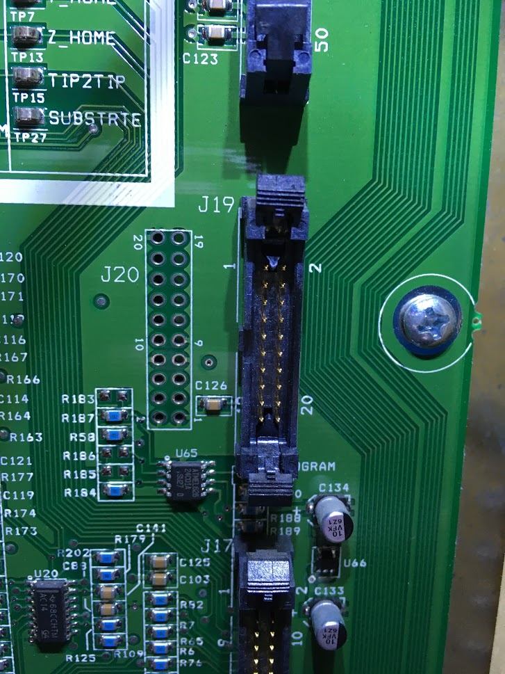
Looking at a photo of the Dimension PDB. Looks like they have the connectors listed as the following (I've also written what they are on the uPrint).
J17 = J15 on uPrint
J19 = J14 on uPrint
J14 = J13 on uPrintWhat you can do to help me:
-
If possible, trace any pins on your power distribution board. If you can find out where the pins go. For example on J13 (J14 on your Dimension) you have all the motor control signals. If you can verify what signals are the same, that will be helpful.
-
Find out what driver chips are present for the stepper motors. On the uPrint they are Allegro A3959 SMD's. On the 1200, they are a different type on those big heatsinks.
-
Likewise, next to the three driver chips, there is a DC servo motor driver. On the uPrint it is a STMicroelectronics L298P. I'm guessing it is the exact same, but if not, let me know.
-
What test points are available, I couldn't see them all on the photo you have on the Github.
On your uPrint: Did you run into any problems with the Stratasys provided +5/12V power supply? I found that the minimum required load for the factory power supply was just too high and then Duet did not draw enough power from it. I had to replace it with a different power supply, I'll have to find the model I used as you may need to also replace yours.
From Github:
-Cons Display firmware doesn't support rotation of 90degrees Expensive
Yes! I've been asking for a long time to see if we can get an option to rotate the display on the PanelDue for the exact reason that it would look better vertical on the uPrint. Maybe if a few of us are requesting it, it can be added? I could not figure out how to do it myself.
See here: https://github.com/dc42/PanelDueFirmware/issues/24
(I did not try what I had suggested there as I was not compiling my own firmware at the time.)
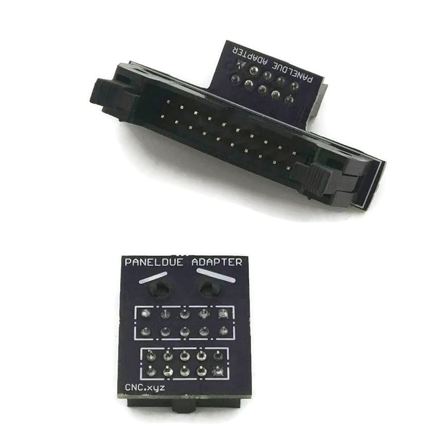
Also. I created plug and play adapters for the PanelDue. The LCD plugs directly into the Stratasys wiring on the uPrint (may be same for Dimension). The ribbon cable coming off of the Stratasys board plugs into the Duet. Check if the ribbon cable on your PDB (looks like J15) is for the front panel. If so, that should work on yours as well.
-
-
@AJ-Quick Awesome work! If only I had space for one of these...
Ian
-
Yeah, it looks quite similar to mine, although the print head board is different.
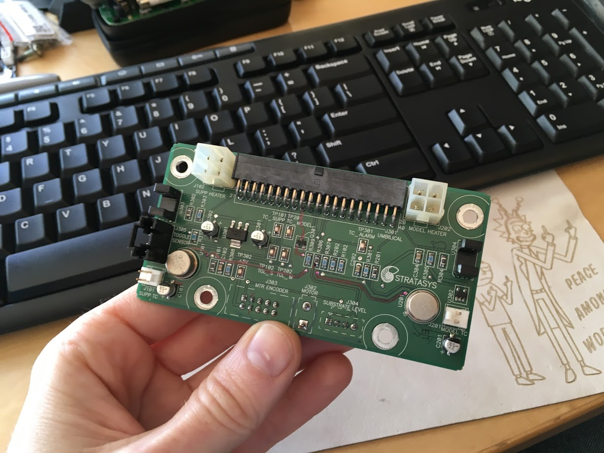
I haven't really cut anything yet, I was going to leave the optical end stops intact and what ever other sensors that I could leave for later use.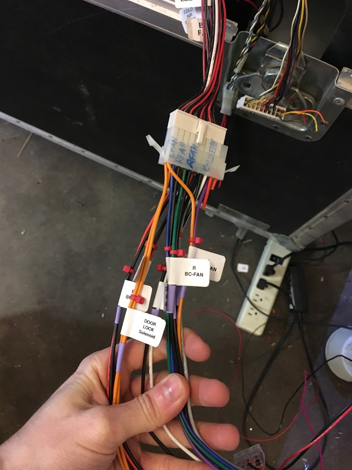
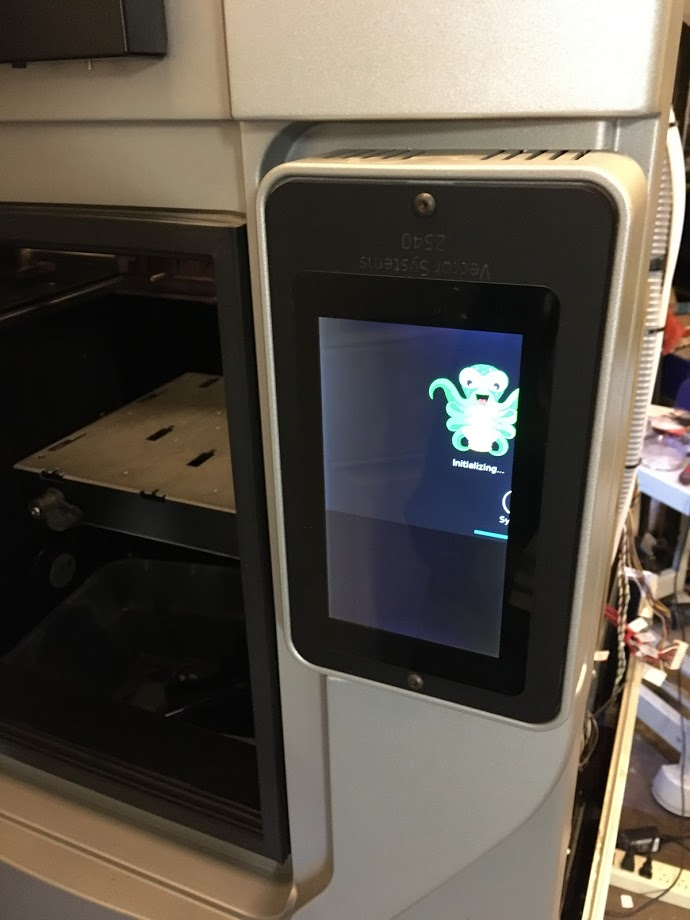
As for the stepper motors I decided it would be far easier to use the Duet TMC drivers and take advantage of the sensorless homing so that I don't have to worry about wiring any of the endstops. It works quite well, and I have the advantage of being able to use the stall guard feature for crash detection during printing.I got rid of the lcd and replaced it with a raspberry pi touchscreen. Unfortunately Octoscreen (octoprint UI) won't run when rotated 90*. The Panel Due does not support 90* rotation either.
 Frustrating.
The stock hotend design is only going to work for printing pc-abs or other high tempature materials that won't deform at lower temperatures. Due to this limitation I'm replacing the extruder assembly with a single hotend for now. I may have a custom 120 watt 24v heater core made for this, the owner of this company is a friend of mine so it makes this easier for me to acquire.
https://ubishotends.com/shop/xx9ppgi6moubdjx5kscfk8md4e8ecb -
It looks to me like the chamber heaters are driven by a mosfet, that first must be enabled by a relay, I',m not completely certain. My goal is to try and tap into the signal inputs for mosfet and relay and wire that to the heated bed output on the duet, that way I wouldn't have to cut any wires.
I see pin 16 of J15 is power enable, I'm assuming that it wants +5v for power enable?
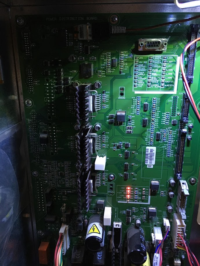
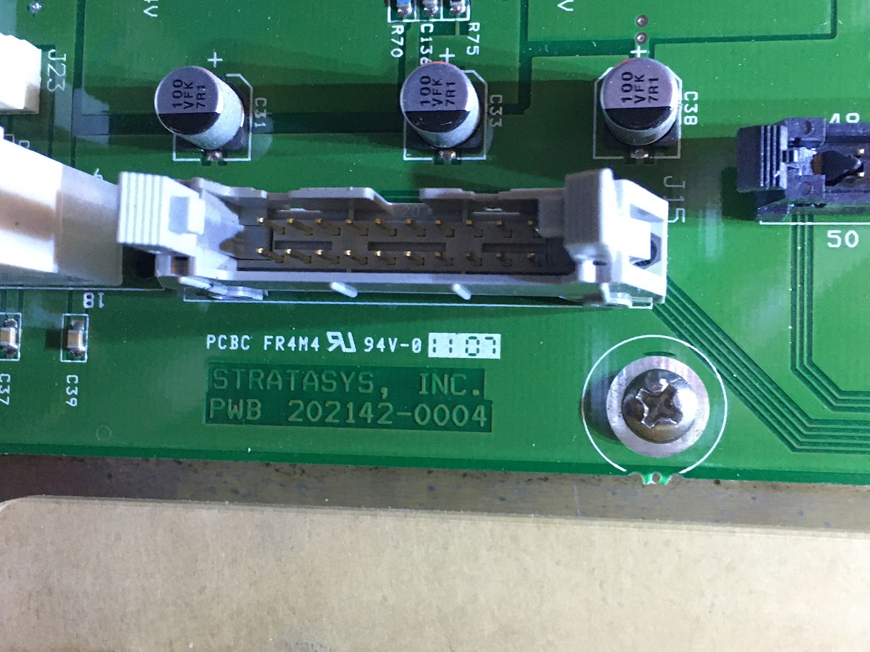
-
My PDB is different than yours, It looks like the ports have different labels. I was able to connect the +5V Reference Test point to Power Enable to power the board on. But that's also powering the Stepper drivers and other things I don't necessarily want turned on. I still need to figure out how to apply power to the Chamber heaters, looks as though the relay to the left of the SSR needs to be enabled first.
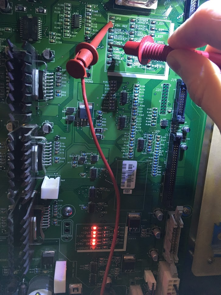
Stepper Drivers
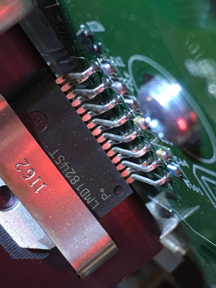
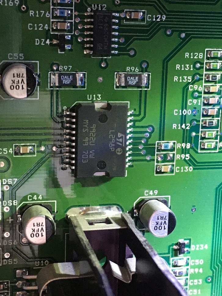
-
@drphil3d said in Another Stratasys uPrint retrofit:
I got rid of the lcd and replaced it with a raspberry pi touchscreen. Unfortunately Octoscreen (octoprint UI) won't run when rotated 90 *. The Panel Due does not support 90 * rotation either. Frustrating.
Perhaps have a look at the DueUi project: https://forum.duet3d.com/topic/13970/dueui-release-3-0-1-beta2-available
-
@drphil3d said in Another Stratasys uPrint retrofit:
Yeah, it looks quite similar to mine, although the print head board is different.

Oh that's interesting. It seems they have combined both the head thermocouple board and the head functions board (power / servo motor / extruder heat.. etc) onto one PCB. On the uPrint they are separate boards.
@drphil3d said in Another Stratasys uPrint retrofit:
As for the stepper motors I decided it would be far easier to use the Duet TMC drivers and take advantage of the sensorless homing so that I don't have to worry about wiring any of the endstops. It works quite well, and I have the advantage of being able to use the stall guard feature for crash detection during printing.
To be honest. That is really easy to do. You can hook the Duet stepper wires up directly to wires coming into the system. I'm not sure if the X, Y and Z motors are on their own connectors like they are on the uPrint. If they are, you can get Molex connectors to plug directly into them. My first test with the uPrint was to make wiring harnesses that connect the motors to the Duet.
That being said. I would still highly recommend keeping all the limit switches in place if at all possible. It should be possible to do both the Duet's drivers and the Stratasys limit switches.
@drphil3d said in Another Stratasys uPrint retrofit:
The stock hotend design is only going to work for printing pc-abs or other high tempature materials that won't deform at lower temperatures. Due to this limitation I'm replacing the extruder assembly with a single hotend for now.
I didn't consider this. Is the stock extruder not able to print PLA and other lower temp materials?
@drphil3d said in Another Stratasys uPrint retrofit:
My PDB is different than yours, It looks like the ports have different labels. I was able to connect the +5V Reference Test point to Power Enable to power the board on. But that's also powering the Stepper drivers and other things I don't necessarily want turned on. I still need to figure out how to apply power to the Chamber heaters, looks as though the relay to the left of the SSR needs to be enabled first.
I don't think there is anything you can do to get around the Stepper Motor drivers from being enabled, other than also enabling the 'all motor drivers sleep' command. If you can't find it, it may be Pin #10 (BRAKE) on the LMD18245 stepper motor driver. Setting that pin logic high (apparently up to 12V) on that chip, may put the drivers to 'sleep'.
The MOSFETS to turn the heaters on/off, LED lights (if equipped), door lock solenoid are located between the stepper motor drivers and the power connections.
From your pictures:
Look at the traces from the touch points and follow them, most of them go to J17. Compare to J15 on the uPrint. You will find most of the touch points are broken out on that connector. This is where you will be able to control the chamber heaters, read the thermocouples, read the limit switches.. etc. Of course you could just as easily solder wires on to the touch points and have them broken out that way too.

If you have a continuity tester:
Connect one end to the touch point and then find continuity back at J17. (Make sure the power is off for this, so you don't short out the connection in J17). For example, the touch point for chamber heat is there, find where it gets broken out on J17. Alternatively, you 'may' be able to jumper power from the +5V ref to the chamber heat touch point to get it to turn on. You may also need to activate the power enabled touch point at the same time.
@Phaedrux said in Another Stratasys uPrint retrofit:
Perhaps have a look at the DueUi project: https://forum.duet3d.com/topic/13970/dueui-release-3-0-1-beta2-available
This is interesting. In my case, I would want to keep everything running on one board with the PanelDue though. That's why I prefer Duet2 vs Duet3.
-
@AJ-Quick said in Another Stratasys uPrint retrofit:
That's why I prefer Duet2 vs Duet3.
Duet3 can run as a standalone board as well btw.
-
I traced the pins and found that J15 is the same as J17 on the 1200SST, I was able to enable the heated chamber and other accessories. Now I face another issue, how do I control it. I can't use the heated bed output on the duet sense that would feed 24v into a 5v pin...aaaahhh.
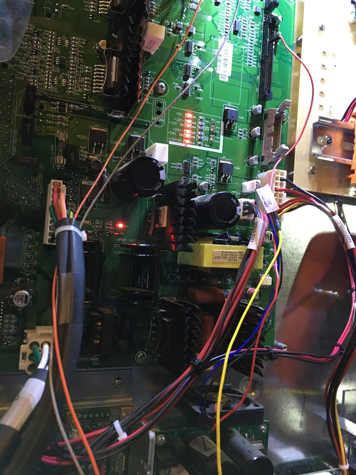
This thing is such a beast
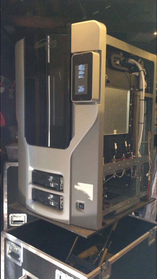
-
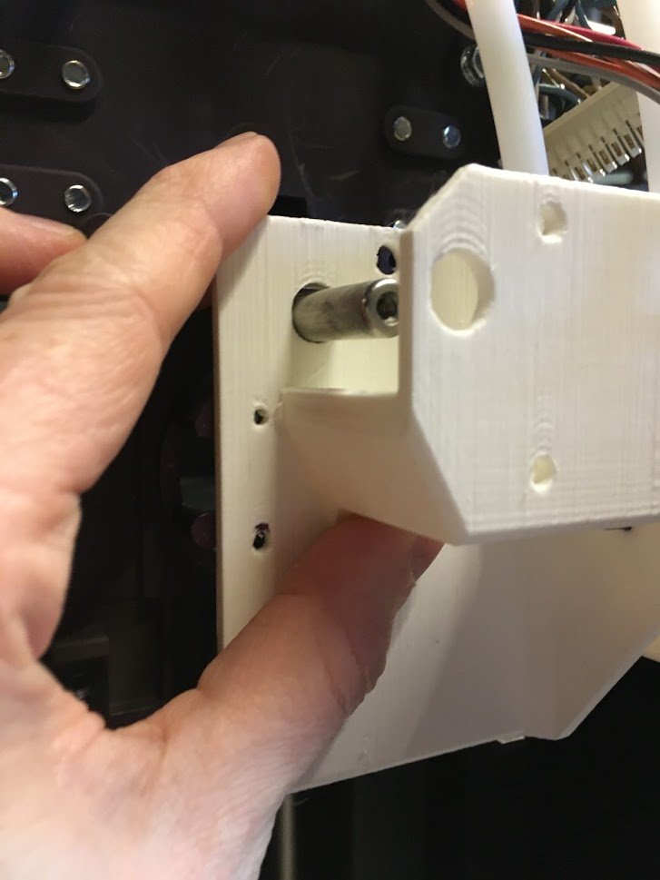
This is my first attempt at a mounting solution for a bondtech bmg extruder. The pin in the middle really gets in the way.
The stock hotend has a number of drawbacks that limit its usefulness.- Not going to print PLA, or anything even the slightest bit flexible the way it's designed. That PC-ABS 430 has a very high glass transition tempature. The oem hotend (liquifier) isn't really meant for printing any low tempature materials.
- non metric nozzle size is going to make slicing interesting
- No or very little retraction. They call it a liquifier for a reason, pc-abs has some unique properties designed for this printhead.
-
@drphil3d said in Another Stratasys uPrint retrofit:
I traced the pins and found that J15 is the same as J17 on the 1200SST.
Great to hear! That's exactly what I was guessing since they both use the same controller board and on-board computer.
@drphil3d said in Another Stratasys uPrint retrofit:
I was able to enable the heated chamber and other accessories. Now I face another issue, how do I control it. I can't use the heated bed output on the duet sense that would feed 24v into a 5v pin...aaaahhh.
The easiest thing you could probably do is connect to a controlled fan output at 5V (this is possible right?). Or get a I/O 3.3v to 5.0v logic level shifter such as the TXS0108E and then connect to the EXT pins.
-
Yeah, that's exactly what I was thinking. Change the jumper to 5V on one of the fan outputs and connect that to the heated chamber, then figure out how to update the config to use the fan pin for chamber heater control.
Another option I was just thinking of, is I could breadboard a transistor and some resistors to signal the chamber heater using one of the 3.3v pins on the duet.
I would drive the heated chamber mosfet directly, however they used a mosfet that has a control voltage limit of 15v, otherwise I could just feed the heated bed output directly to the heated chamber test point pin (TP2).